


Metal detector with 555
#metal detector
#555 timer
#magnet detection
#frequency change
#10mH choke
#sensor circuit
#electronic detection
#inductive sensor
#pulse circuit
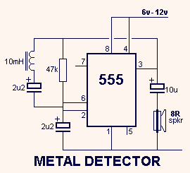
Description: This circuit detects metal and also magnets. When a magnet is brought close to the 10mH choke, the output frequency changes.
The circuit operates on the principle of inductance variation in response to the presence of a magnetic field. The core component is a 10mH choke, which is an inductor designed to resist changes in current. When a magnet approaches the choke, the magnetic field interacts with the inductor, resulting in a change in inductance. This change affects the resonant frequency of the circuit, which can be detected and measured.
The circuit typically includes a signal generator, which produces an oscillating signal at the resonant frequency of the inductor. The output from the inductor is fed into a frequency detection circuit, which could be implemented using a microcontroller or a dedicated frequency counter. The detection circuit monitors the frequency of the output signal and triggers an alert or activates a response mechanism when a significant deviation from the baseline frequency is detected.
To enhance sensitivity and reduce false positives, additional components such as capacitors may be included to form a resonant LC circuit with the inductor. The values of these components can be adjusted to fine-tune the circuit's response to specific magnetic fields or metal types. A comparator circuit may also be integrated to provide a clear digital output based on the detected frequency change, allowing for easy interfacing with other electronic systems or alarms.
This type of metal and magnet detection circuit can be utilized in various applications, including security systems, industrial automation, and proximity sensing in consumer electronics.This circuit detects metal and also magnets. When a magnet is brought close to the 10mH choke, the output frequency changes.
The circuit operates on the principle of inductance variation in response to the presence of a magnetic field. The core component is a 10mH choke, which is an inductor designed to resist changes in current. When a magnet approaches the choke, the magnetic field interacts with the inductor, resulting in a change in inductance. This change affects the resonant frequency of the circuit, which can be detected and measured.
The circuit typically includes a signal generator, which produces an oscillating signal at the resonant frequency of the inductor. The output from the inductor is fed into a frequency detection circuit, which could be implemented using a microcontroller or a dedicated frequency counter. The detection circuit monitors the frequency of the output signal and triggers an alert or activates a response mechanism when a significant deviation from the baseline frequency is detected.
To enhance sensitivity and reduce false positives, additional components such as capacitors may be included to form a resonant LC circuit with the inductor. The values of these components can be adjusted to fine-tune the circuit's response to specific magnetic fields or metal types. A comparator circuit may also be integrated to provide a clear digital output based on the detected frequency change, allowing for easy interfacing with other electronic systems or alarms.
This type of metal and magnet detection circuit can be utilized in various applications, including security systems, industrial automation, and proximity sensing in consumer electronics.This circuit detects metal and also magnets. When a magnet is brought close to the 10mH choke, the output frequency changes.
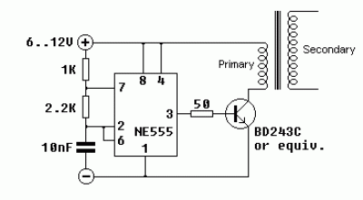
555 circuits 6
The core component of this circuit is the 555 timer IC. The alert sound does not stop immediately when the switch is activated; instead, it ceases automatically after a predetermined time period, which is set by the resistance of R3....
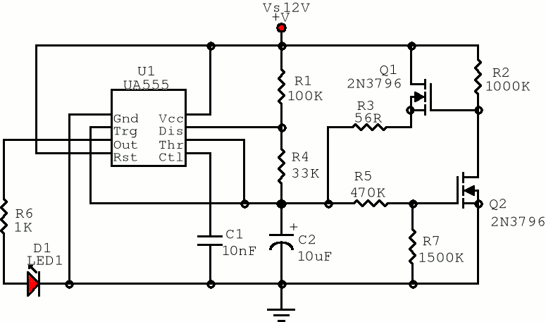
555 Pulse generator
The first positive pulse from a classic 555-based oscillator is always 1.6 times longer than the subsequent pulses. This discrepancy occurs because, during the initial cycle, capacitor C2 begins charging from 0 V. While this is typically not an issue,...
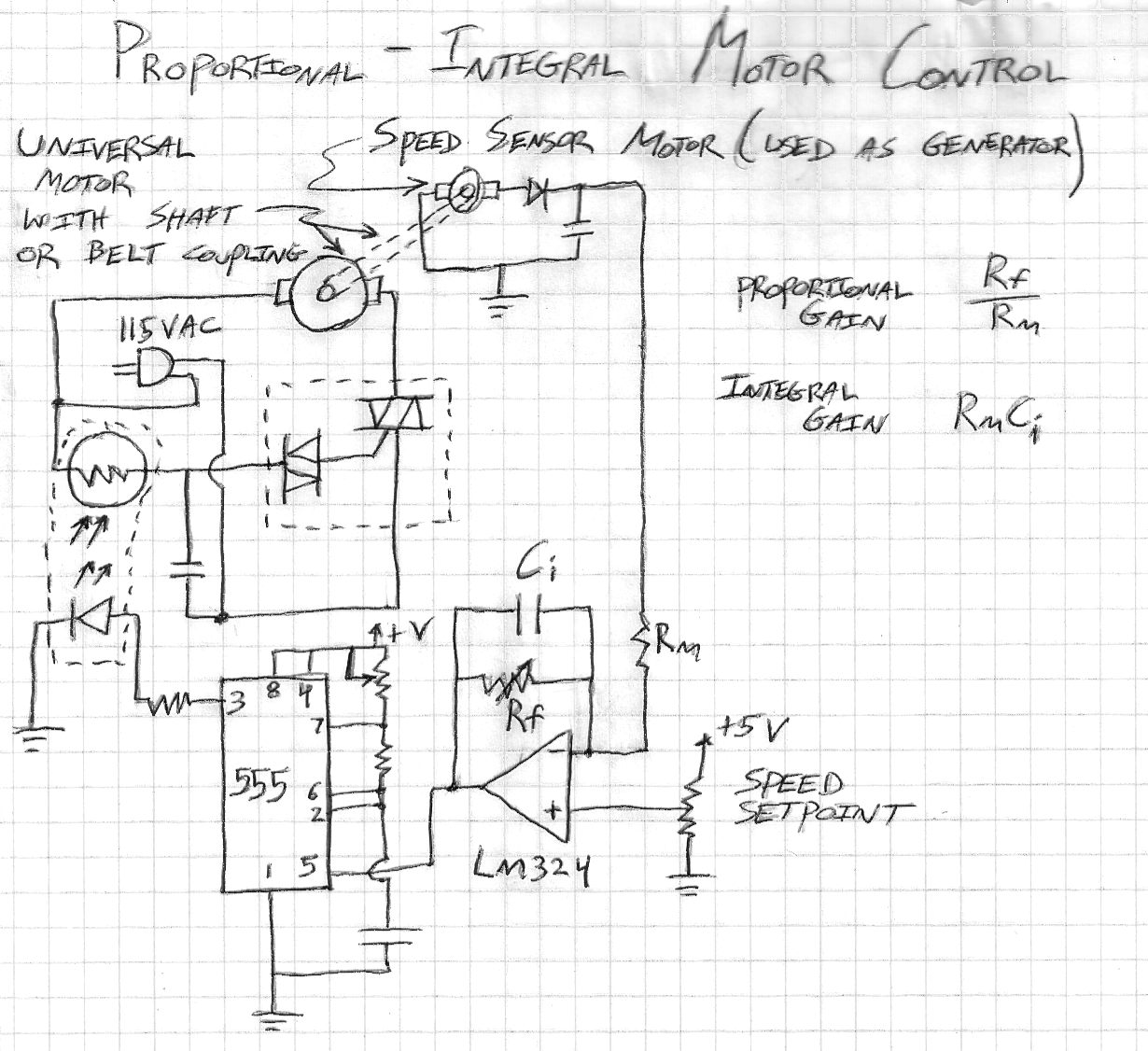
555 Timer Contest Entry
This is a motor speed control circuit that enables safe and straightforward regulation of 115VAC universal motors, such as those found in drill motors, blender motors, and other power tools. The motor is directly controlled by a triac-diac component commonly...
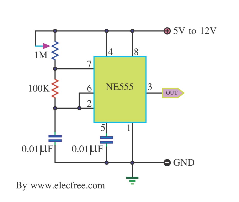
Simple Pulse Generator by IC 555 Timer
This is a simple pulse generator circuit or standard astable oscillator circuit for the IC 555 timer, NE555N IC.
The astable oscillator circuit utilizing the NE555 timer IC serves as a versatile pulse generator, producing a continuous square wave output....
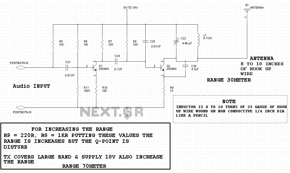
Solid State Power Controllers
The circuit is constructed using two 555 timer integrated circuits (ICs), designated as U1 and U2. U1 is configured as a variable duty cycle oscillator with a fixed time period of approximately 0.1 seconds. The duty cycle can be adjusted...
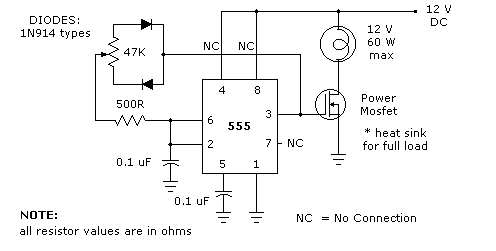
LIGHT DIMMER
The 555 timer light dimmer schematic circuit is shown in figure 1 below. For the light dimmer to work, the 555 timer is configured as a variable cycle astable oscillator running somewhere around 300 Hz. The power MOSFET used here...
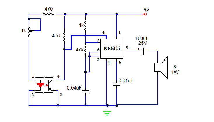
SMOKE DETECTOR USING 555 TIMER
This document presents a simple smoke sensing alarm circuit utilizing a 555 timer. The circuit is designed to detect smoke and trigger an alarm when the air is contaminated. The components employed in this design include an astable multivibrator and...
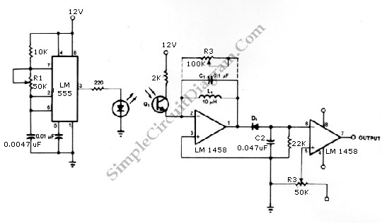
555 Infrared Transmitter-Receiver
The infrared transmitter and receiver circuit depicted in the schematic diagram below can function as a remote control. The transmitter primarily operates as an oscillator.
The infrared transmitter and receiver circuit is designed to facilitate wireless communication through infrared signals, making...
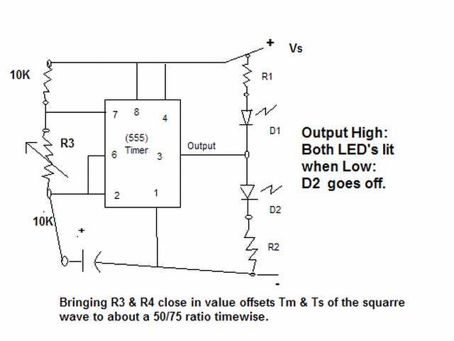
555 timer as a flip-flop
The output signal is configured to go high for approximately 0.5 seconds and then low for around 1.33 seconds. However, there is an issue present.
The circuit in question likely employs a timing mechanism to achieve the specified output signal behavior....