


16C71 IC For Experimenting With A Simple DC Servo Motor
#PIC 16C71
#servo motor
#DC motor
#control
#software programming
#0-5V
#microcontroller
#motor control
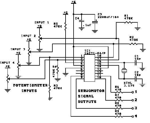
Description: This involves controlling servo motors through software programming using the PIC 16C71 microcontroller. The input signals range from 0 to 5V.
The circuit utilizes the PIC 16C71 microcontroller, which is an 8-bit device suitable for controlling servo motors. The microcontroller operates on a supply voltage within the range of 4 to 5.5V, making it compatible with the 0 to 5V input signals typically used for servo control.
To initiate control, the microcontroller generates Pulse Width Modulation (PWM) signals. The duty cycle of these PWM signals determines the position of the servo motor. For instance, a 1.5ms pulse corresponds to the neutral position of the servo, while shorter or longer pulses (1ms or 2ms) will rotate the servo to its extreme positions (0° or 180°).
The circuit design includes a power supply unit that provides the necessary voltage to the microcontroller and servo motors. It is essential to ensure that the current rating of the power supply meets the requirements of the servo motors, particularly under load conditions.
Input signals may be derived from various sources such as potentiometers, switches, or other sensors that output a voltage within the specified range. These signals are fed into the microcontroller’s analog-to-digital converter (ADC) or directly into the GPIO pins, depending on the design. The microcontroller processes these inputs and adjusts the PWM output accordingly.
In addition to the microcontroller and servo motors, the circuit may incorporate additional components such as resistors for signal conditioning, capacitors for noise filtering, and diodes for protection against back EMF generated by the motors. Proper PCB layout and grounding practices should be followed to minimize interference and ensure reliable operation.
This configuration allows for precise control of servo motors in various applications, including robotics, automation, and remote control systems. The flexibility of the PIC 16C71 microcontroller enables the implementation of complex control algorithms, enhancing the performance and functionality of the servo control system.This is a control of servo motors in software programming using PIC 16C71 microcontroller. The input signals are between 0 - 5V delivered by ..
The circuit utilizes the PIC 16C71 microcontroller, which is an 8-bit device suitable for controlling servo motors. The microcontroller operates on a supply voltage within the range of 4 to 5.5V, making it compatible with the 0 to 5V input signals typically used for servo control.
To initiate control, the microcontroller generates Pulse Width Modulation (PWM) signals. The duty cycle of these PWM signals determines the position of the servo motor. For instance, a 1.5ms pulse corresponds to the neutral position of the servo, while shorter or longer pulses (1ms or 2ms) will rotate the servo to its extreme positions (0° or 180°).
The circuit design includes a power supply unit that provides the necessary voltage to the microcontroller and servo motors. It is essential to ensure that the current rating of the power supply meets the requirements of the servo motors, particularly under load conditions.
Input signals may be derived from various sources such as potentiometers, switches, or other sensors that output a voltage within the specified range. These signals are fed into the microcontroller’s analog-to-digital converter (ADC) or directly into the GPIO pins, depending on the design. The microcontroller processes these inputs and adjusts the PWM output accordingly.
In addition to the microcontroller and servo motors, the circuit may incorporate additional components such as resistors for signal conditioning, capacitors for noise filtering, and diodes for protection against back EMF generated by the motors. Proper PCB layout and grounding practices should be followed to minimize interference and ensure reliable operation.
This configuration allows for precise control of servo motors in various applications, including robotics, automation, and remote control systems. The flexibility of the PIC 16C71 microcontroller enables the implementation of complex control algorithms, enhancing the performance and functionality of the servo control system.This is a control of servo motors in software programming using PIC 16C71 microcontroller. The input signals are between 0 - 5V delivered by ..
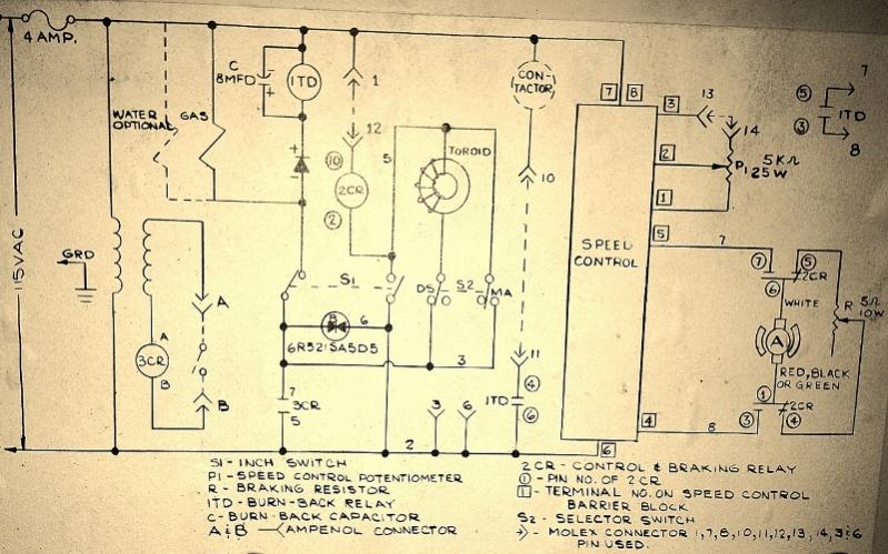
salvage dc motor speed control
A Chemetron wire feeder is being utilized, and there is a desire to use the speed control from the control box to regulate the motor it originally contained.
The Chemetron wire feeder is designed for efficient wire feeding in welding applications....
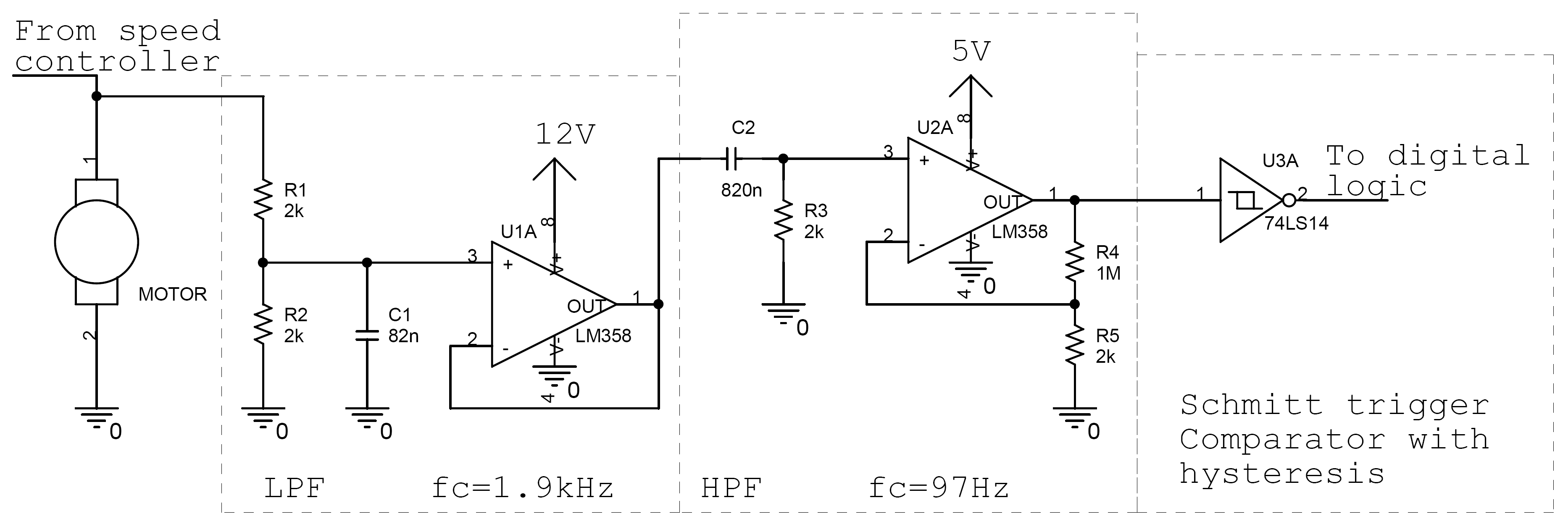
DC Motor Controller and Tachometer
Controlling the speed of a motor is crucial in various applications, particularly in robotics. Numerous techniques exist for adjusting motor speed, each offering distinct advantages and disadvantages. This document outlines the construction of a motor controller that regulates the speed...
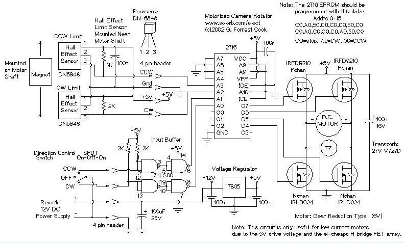
Motorized Video Camera Mount
The camera rotator circuit utilizes a 2716 EPROM to store a logic value table that governs the motor driver (H-bridge) circuit. The schematic illustrates the EPROM data. By employing the EPROM, a significant number of discrete gates are eliminated. The...
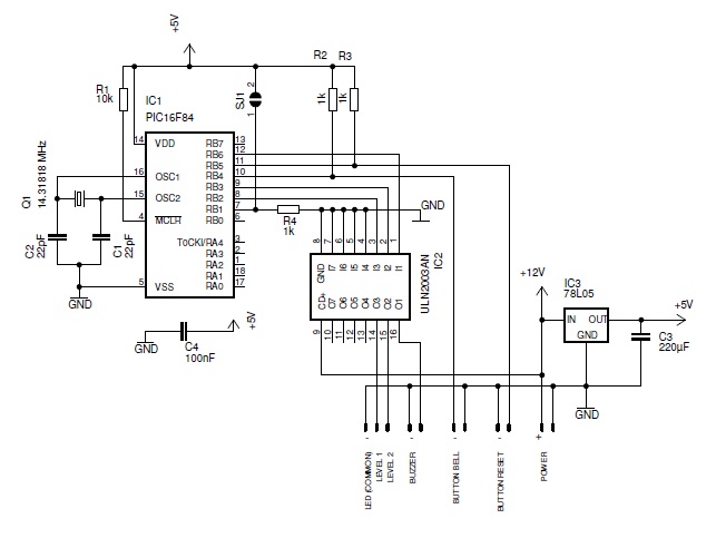
doorbel
This smart doorbell system is designed for use in industrial environments. It is microcontroller-based and controls a horn and a flashlight.
The smart doorbell system utilizes a microcontroller to manage its operations, making it suitable for industrial applications where reliability and...
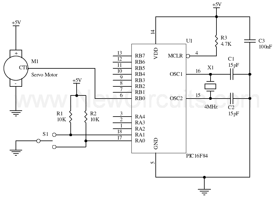
Servo Motor Control with PIC16F84
This simple microcontroller circuit regulates a servo motor based on a 3-state switch. The servo motor functions as an actuator with three positions. It consists of three wires: one for VCC, one for ground, and a third for position control....
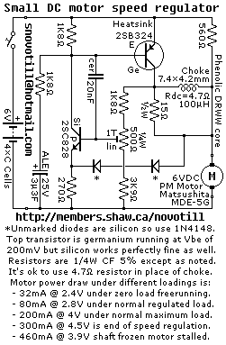
Small DC Motor Speed Regulator
Reverse engineered circuit diagram of a motor speed regulator out of a portable pocket tape recorder containing a single motor for all functions. This circuit works amazingly well, keeping the motor speed constant regardless of shaft load and battery voltage.
The...
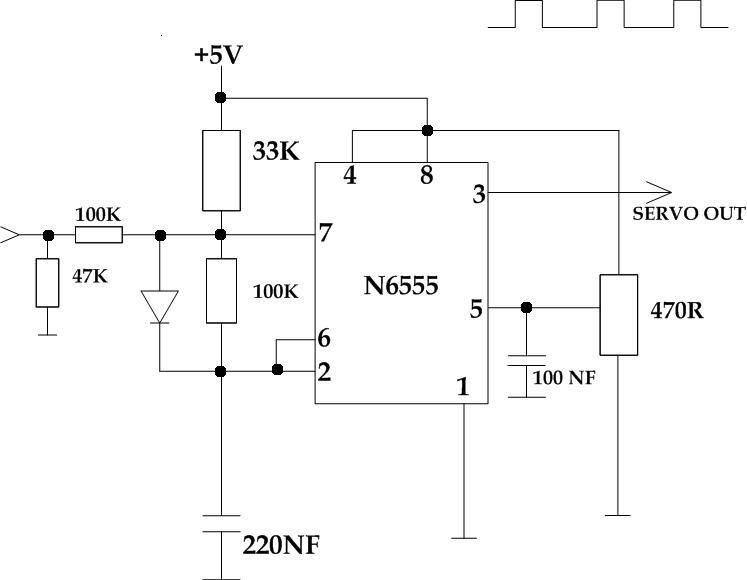
Servo controlling circuit
This circuit takes a standard 0-10V control voltage (for example, from an analog light control desk) and outputs a standard 1-2 ms control pulse for RC servo motors. The components used in this circuit include:
- 2 x 100 kΩ...
home security system
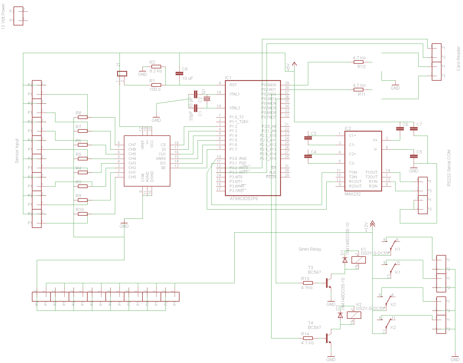
The fundamental design of this project employs an Atmel AT89S8252-24PC Microcontroller, which features 2KB of EEPROM for runtime data storage. An ADC0838CCN analog-to-digital converter will be utilized to process up to eight inputs from sensor devices, including passive infrared sensors...
Robo Atmega328p project
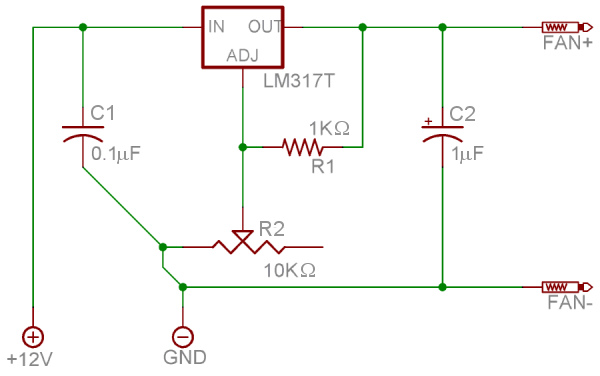
This project was designed to introduce a friend to microcontrollers and circuits using various functionalities and spare parts. A PS2 numpad was utilized as the key entry mechanism, which was found at a thrift store and included the necessary connector....