


AT89xx051 PROGRAMMER
#AT89xx051
#programmer
#voltage regulator
#capacitor
#7812
#15VDC
#bypass diode
#reverse voltage protection
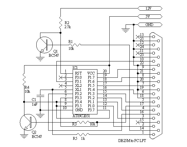
Description: A 15V DC adapter is required. An electrolytic capacitor should be placed across the input of the voltage regulator. If a capacitor is connected to the output pin of the 7812 voltage regulator with respect to ground, a bypass diode must be added in reverse orientation between the input and output of the regulator to protect it from reverse voltage.
The circuit requires a 15V DC power supply, which serves as the input voltage for the voltage regulator, specifically the 7812 model. The 7812 voltage regulator is designed to output a stable 12V DC from a higher voltage input. To ensure proper operation and stability of the voltage regulator, an electrolytic capacitor is recommended across the input terminals of the regulator. This capacitor helps filter out any voltage spikes or fluctuations from the power supply, providing a smoother input voltage to the regulator.
When a capacitor is connected to the output pin of the 7812 with respect to ground, it is essential to include a bypass diode. This diode should be connected in reverse orientation between the input and output pins of the regulator. The purpose of this diode is to prevent any potential reverse voltage that may occur, which could damage the regulator. In normal operation, the diode remains reverse-biased, effectively isolating the input from the output. However, in the event of a fault condition or sudden voltage drop, the diode will conduct, protecting the regulator from reverse voltage and ensuring reliable circuit performance.
In summary, this circuit configuration emphasizes the importance of using an electrolytic capacitor for input stability and a bypass diode for protection against reverse voltage, thus ensuring the longevity and reliability of the 7812 voltage regulator in various applications.It requires a 15VDC adapter. An electrolyte capacitor is needed across the regulator input. If the capacitor is added in 7812`s OUT pin w. r. t. ground, then a bypass diode should be added in reverse to IN and OUT of the regulator, just to save it from reverse voltage.
The circuit requires a 15V DC power supply, which serves as the input voltage for the voltage regulator, specifically the 7812 model. The 7812 voltage regulator is designed to output a stable 12V DC from a higher voltage input. To ensure proper operation and stability of the voltage regulator, an electrolytic capacitor is recommended across the input terminals of the regulator. This capacitor helps filter out any voltage spikes or fluctuations from the power supply, providing a smoother input voltage to the regulator.
When a capacitor is connected to the output pin of the 7812 with respect to ground, it is essential to include a bypass diode. This diode should be connected in reverse orientation between the input and output pins of the regulator. The purpose of this diode is to prevent any potential reverse voltage that may occur, which could damage the regulator. In normal operation, the diode remains reverse-biased, effectively isolating the input from the output. However, in the event of a fault condition or sudden voltage drop, the diode will conduct, protecting the regulator from reverse voltage and ensuring reliable circuit performance.
In summary, this circuit configuration emphasizes the importance of using an electrolytic capacitor for input stability and a bypass diode for protection against reverse voltage, thus ensuring the longevity and reliability of the 7812 voltage regulator in various applications.It requires a 15VDC adapter. An electrolyte capacitor is needed across the regulator input. If the capacitor is added in 7812`s OUT pin w. r. t. ground, then a bypass diode should be added in reverse to IN and OUT of the regulator, just to save it from reverse voltage.
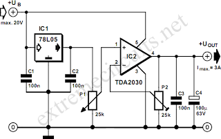
Adjustable 3 Ampere Regulator
By combining a standard 78L05 voltage regulator with an integrated audio amplifier, specifically the TDA2030, it is possible to construct a simple yet effective adjustable voltage regulator. This regulator can output a voltage adjustable up to 20 V and handle...
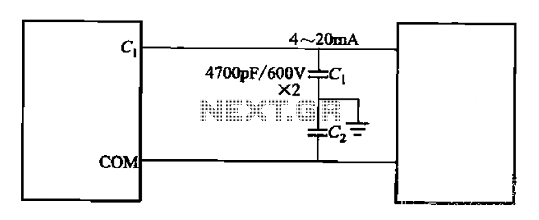
Control cables plus anti-interference capacitors
A capacitor filter is utilized in frequency control circuits and is a common method for implementing anti-jamming measures. It addresses frequency interference noise within the wiring of the 4-20mA control loop. The anti-interference is achieved through bypass capacitors C1 and...
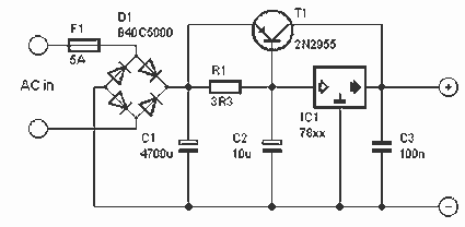
5 A stabilized power supply
This is a simple but powerful nutrition that less than 5 A can deliver. The circuit works by using a normal type 78xx voltage regulator and a buffer transistor. When the output current over 200 mA, then take over the...
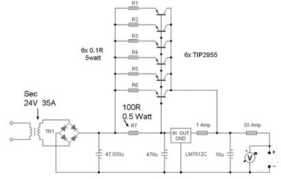
35 Ampere Power Supply
A 12 Volt 35 Amp power supply can be constructed using the LM7812 voltage regulator to provide a stable 12 Volt DC output. The power supply employs TIP2955 transistors as the main power regulators, with a configuration that utilizes six...
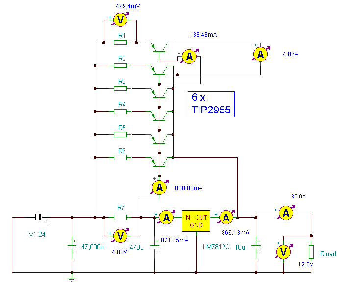
12 Volt 30 Amp Power Supply
This power supply utilizes a single 7812 integrated circuit (IC) voltage regulator in conjunction with multiple external pass transistors to provide output load currents of up to 30 amps.
The circuit design incorporates a 7812 voltage regulator, which is known for...
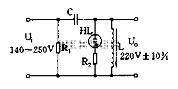
Easy exchange of magnetic saturation voltage regulator circuit
Easy exchange of magnetic saturation voltage regulator circuit
The magnetic saturation voltage regulator circuit is designed to stabilize output voltage levels by utilizing magnetic saturation principles. This circuit typically employs a magnetic core, which operates in saturation to regulate voltage,...
own capacitor
The capacitor is composed of two sheets of aluminum foil. It is essential to keep the foil within the plastic packets and connect them using crocodile clips, ensuring that the clips do not touch each other. The initial frequency of...
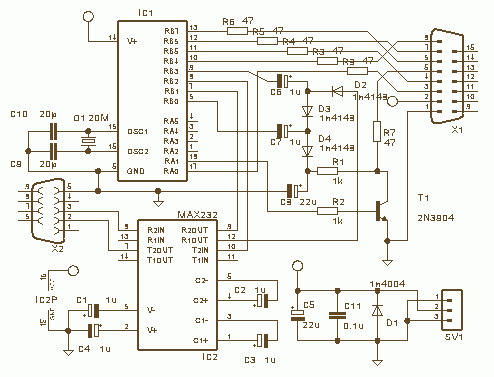
Wisp628
Wisp628 is designed to be used as an in-circuit programmer only, hence no socket is provided for the target chip. Why use such a limited design, you might ask, an ex-circuit programmer with a ZIF socket can do the same...
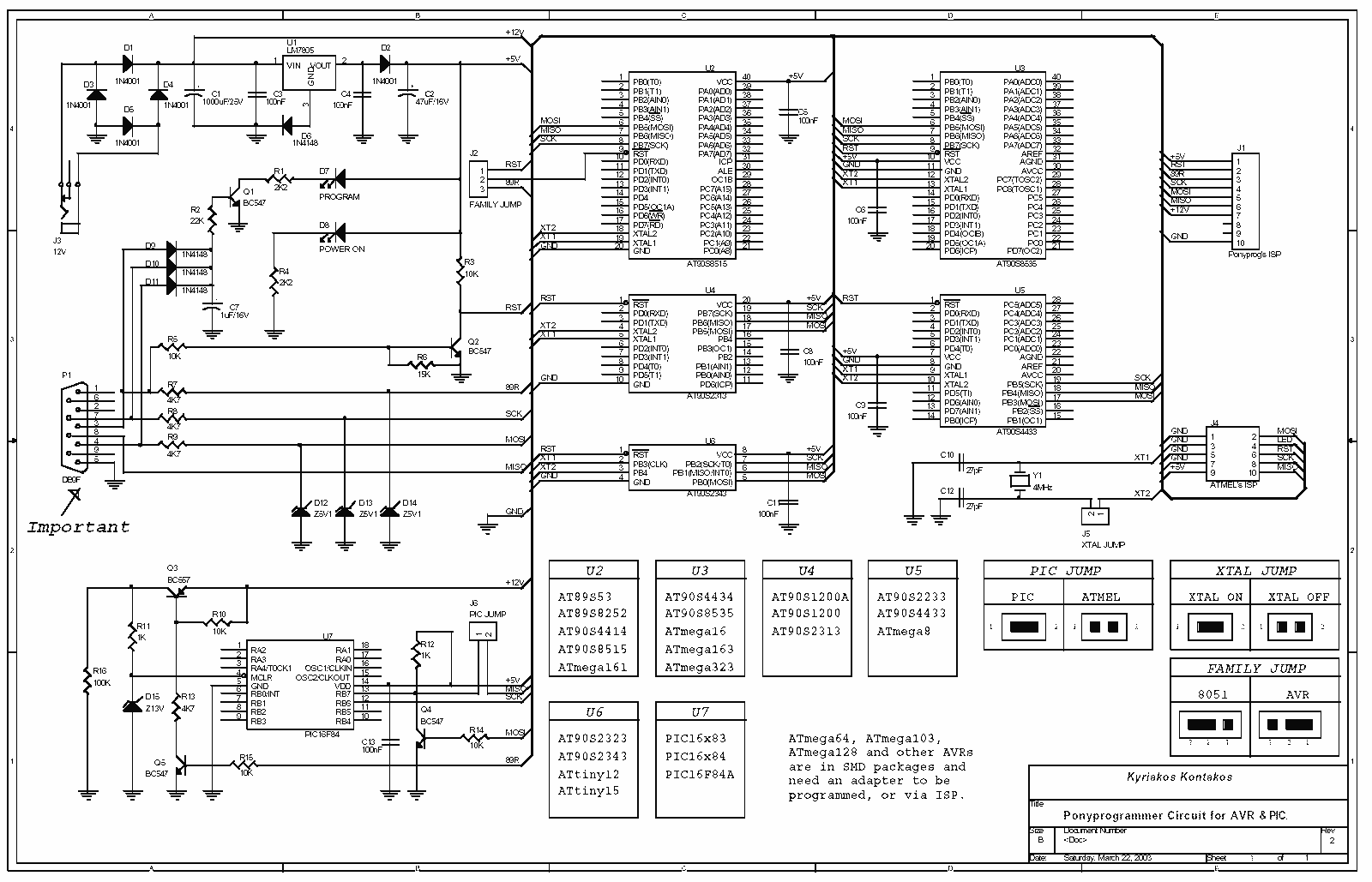
Ponyprog for AVR & PIC16F84
All resistors are 1/4W. The circuit is powered by 9...15V DC or AC. When In Circuit Programming (ISP) connectors are used, it is possible for the programmer to be powered from the target's power source. Diodes D2 and D6 protect...