


ATmega32u2 USB powered how to ground
#ATmega32u2
#USB power
#grounding
#MCU
#voltage regulation
#circuit design
#embedded systems
#power management
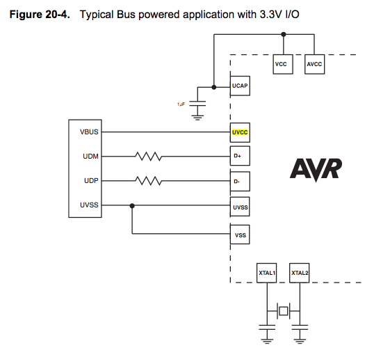
Description: Since the microcontroller unit (MCU) is powered through USB, the common zero voltage should align with the supply voltage and thus be connected to the 0V (UVSS) line.
In electronic circuit design, it is essential to ensure that the ground reference points are consistent throughout the system. When powering a microcontroller unit (MCU) via a USB connection, the common ground (zero voltage reference) must be connected to the supply voltage ground. This is critical to prevent potential ground loops and ensure proper operation of the MCU.
The USB interface typically provides a power supply of 5V, which is the standard voltage level for many microcontrollers. The 0V line, also referred to as the UVSS line, serves as the reference point for all voltage levels in the circuit. Properly connecting the UVSS line to the common ground of the USB power supply ensures that the MCU can accurately interpret signal levels and operate reliably.
In practical implementation, the circuit should include bypass capacitors near the MCU power pins to filter out noise and stabilize the power supply. Additionally, careful routing of ground traces is necessary to minimize inductance and maintain a low-resistance path to ground. This layout consideration is vital for high-speed digital circuits, where signal integrity can be adversely affected by poor grounding practices.
Furthermore, it is advisable to include protection components such as diodes to safeguard the MCU from potential overvoltage conditions that may arise from the USB connection. This protection will enhance the robustness of the circuit, ensuring that the MCU remains functional even under unexpected electrical conditions.
Overall, maintaining a consistent ground reference by connecting the common zero voltage to the UVSS line is a fundamental practice in electronic circuit design, particularly when integrating USB-powered microcontrollers.Because you are powering the MCU via USB, this common zero voltage should be the same as the supply and therefore connected to the 0V (UVSS) line.
In electronic circuit design, it is essential to ensure that the ground reference points are consistent throughout the system. When powering a microcontroller unit (MCU) via a USB connection, the common ground (zero voltage reference) must be connected to the supply voltage ground. This is critical to prevent potential ground loops and ensure proper operation of the MCU.
The USB interface typically provides a power supply of 5V, which is the standard voltage level for many microcontrollers. The 0V line, also referred to as the UVSS line, serves as the reference point for all voltage levels in the circuit. Properly connecting the UVSS line to the common ground of the USB power supply ensures that the MCU can accurately interpret signal levels and operate reliably.
In practical implementation, the circuit should include bypass capacitors near the MCU power pins to filter out noise and stabilize the power supply. Additionally, careful routing of ground traces is necessary to minimize inductance and maintain a low-resistance path to ground. This layout consideration is vital for high-speed digital circuits, where signal integrity can be adversely affected by poor grounding practices.
Furthermore, it is advisable to include protection components such as diodes to safeguard the MCU from potential overvoltage conditions that may arise from the USB connection. This protection will enhance the robustness of the circuit, ensuring that the MCU remains functional even under unexpected electrical conditions.
Overall, maintaining a consistent ground reference by connecting the common zero voltage to the UVSS line is a fundamental practice in electronic circuit design, particularly when integrating USB-powered microcontrollers.Because you are powering the MCU via USB, this common zero voltage should be the same as the supply and therefore connected to the 0V (UVSS) line.
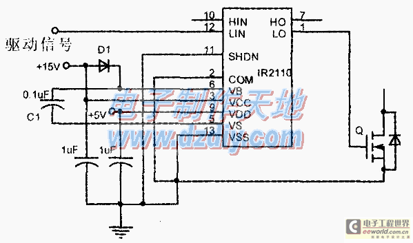
Design and making of the stabilized voltage supply of switch
Under the loading condition of the resistance, the output voltage (Uo) variable range is from 30V to 36V, with a maximum output current (Imax) of 2A. When the input voltage (U2) changes from 15V to 21V, the voltage regulation factor...
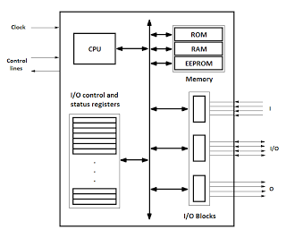
microcontrollers
Microcontrollers are integrated circuits that consist of a microprocessor along with additional units such as memory and input/output peripherals. This implementation allows for savings in time, space, and cost. Microcontrollers are commonly abbreviated as MCU (Microcontroller Unit), µC, or uC....
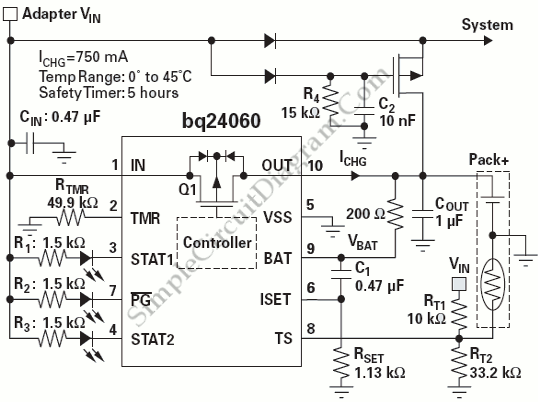
Power Path Management Battery Charger
Powering the system is required by many applications while charging the battery simultaneously. Interaction between the system and charger may result in a...
Power management in electronic systems is critical, particularly in applications that necessitate simultaneous operation and battery charging. This...
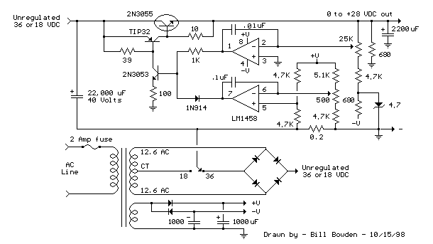
variable voltage and current power supply
An alternative method for utilizing operational amplifiers (op-amps) to regulate a power supply is illustrated below. The power transformer necessitates an additional winding to provide the op-amps with a bipolar voltage of +/- 8 volts. This negative voltage is also...
Power Path Management Battery Charger
Powering the system is required by many applications while charging the battery simultaneously. Interaction between the system and charger may result in a...
Power management in electronic systems is critical, particularly in applications that necessitate simultaneous operation and battery charging. This...
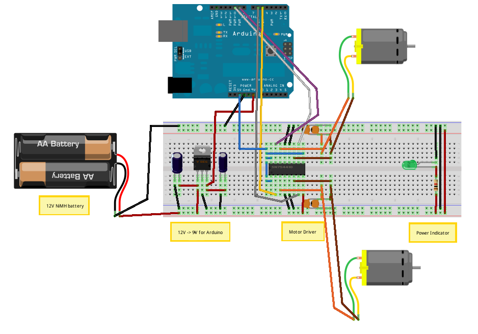
Voltage Regulators
Until Willow Garage was acquired, there was work as a Web Robotics Engineer. This title reflects a role as a full-stack engineer focused on real-time, distributed robot control. Notable projects include an XML-RPC server and client for Node.js, a deprecated...
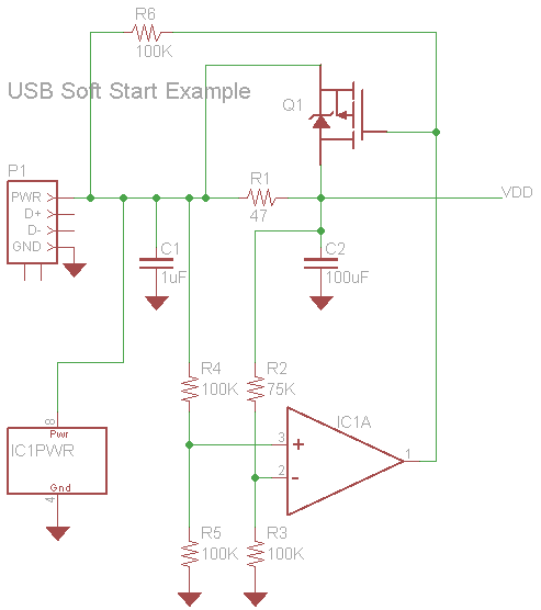
USB powered device with multiple Decoupling Capacitors
A USB powered device with multiple integrated circuits (ICs). It is standard practice to use a combination of various range capacitors for decoupling each individual IC, with the smallest capacitors placed as close as possible to the ICs and larger...
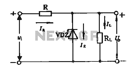
Regulator circuit silicon resistor formed
The simple voltage regulator circuit consists of a silicon regulator and a resistor. It is designed to rectify and filter DC voltage, as illustrated in the accompanying figure. The voltage regulator is connected in parallel with the load, and the...
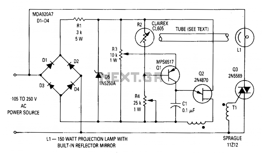
Voltage regulator for projection lamp
The circuit regulates the RMS output voltage across a load, specifically a projection lamp, to 100 volts ±2% for input voltages ranging from 105 to 250 volts AC. This regulation is achieved by indirectly sensing the light output of lamp...