


Attiny2313 based LAN cable tester
#Attiny2313
#LAN cable tester
#RJ45
#assembly code
#network testing
#microcontroller
#schematic
#source code
#port D
#cable diagnostics
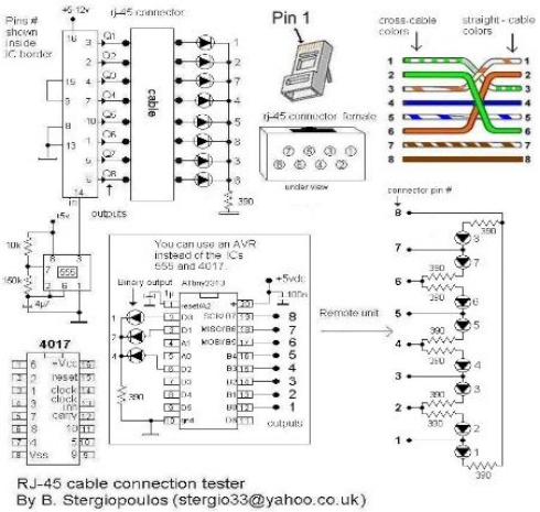
Description: Vasilis Stergiopoulos has developed an RJ45 LAN cable tester. The circuit was initially designed to utilize a 555 timer and a 4017 decade counter IC, but Vasilis has released a schematic and assembly source code for implementing the Attiny2313 microcontroller instead. The Attiny2313 generates sequential outputs at port D, where the LAN cable is connected. When a straight cable is connected between connectors A and B, the LEDs will illuminate in a sequential order. Conversely, if a crossover cable is connected, the LEDs will light up in the specified order on the board: 1, 2, 7, 4, 5, 8, 3, 6. Any other illumination sequence indicates that the cable is incorrectly wired. If one or more LEDs do not light up, this indicates an open circuit. A remote unit with only the B connector (B2) can be utilized if both ends of the cable are not accessible in the same location.
The RJ45 LAN cable tester designed by Vasilis Stergiopoulos is a practical tool for verifying the integrity and wiring configuration of Ethernet cables. The core of the circuit utilizes the Attiny2313 microcontroller, which is programmed to control the sequencing of LED indicators based on the connectivity of the cable. The device operates by connecting the cable under test between two connectors labeled A and B.
In a straightforward wiring scenario, the LEDs will illuminate in a predictable sequence, allowing users to confirm that the cable is wired correctly. The specific LED sequence for a straight-through connection is designed to provide a clear visual confirmation of each wire's continuity and proper termination.
In contrast, when a crossover cable is connected, the LED sequence will differ, illuminating in the order specified on the board. This feature is crucial for technicians who need to identify the type of cable quickly and ascertain whether it is functioning correctly.
The testing circuit also includes functionality to detect faults such as open circuits. If any LED fails to illuminate, it signals a problem in the corresponding wire within the cable, alerting the user to potential issues that may need to be addressed.
For scenarios where access to both ends of the cable is limited, the design incorporates a remote unit with only the B connector (B2). This allows testing to be performed from a single location, enhancing the convenience and applicability of the tester in various environments, such as in-wall installations or hard-to-reach areas.
Overall, the RJ45 LAN cable tester is a valuable device for network professionals, providing a reliable means of ensuring cable integrity and proper wiring configurations.Vasilis Stergiopoulos has built a RJ45 LAN cable tester. The circuit was originally designed to use a 555 and 4017 IC, but Vasilis has published the schematic and source code in assembly for using the Attiny2313 instead. The Attiny2313 produces successive outputs at port D, where the LAN-cable is connected. If a straight cable is connected between connectors A and B, then the LEDs will glow in successive order. If a cross cable is connected, then the glow order will be as noted on the board, i. e. 1, 2, 7, 4, 5, 8, 3, 6. If any other glow order occurs, it means that the cable is not wired correctly. If one or more LEDs don`t glow, then we have a corresponding open circuit. A remote unit with only the B connector (B2) can be used if both cable ends are not accessible in the same location.
The RJ45 LAN cable tester designed by Vasilis Stergiopoulos is a practical tool for verifying the integrity and wiring configuration of Ethernet cables. The core of the circuit utilizes the Attiny2313 microcontroller, which is programmed to control the sequencing of LED indicators based on the connectivity of the cable. The device operates by connecting the cable under test between two connectors labeled A and B.
In a straightforward wiring scenario, the LEDs will illuminate in a predictable sequence, allowing users to confirm that the cable is wired correctly. The specific LED sequence for a straight-through connection is designed to provide a clear visual confirmation of each wire's continuity and proper termination.
In contrast, when a crossover cable is connected, the LED sequence will differ, illuminating in the order specified on the board. This feature is crucial for technicians who need to identify the type of cable quickly and ascertain whether it is functioning correctly.
The testing circuit also includes functionality to detect faults such as open circuits. If any LED fails to illuminate, it signals a problem in the corresponding wire within the cable, alerting the user to potential issues that may need to be addressed.
For scenarios where access to both ends of the cable is limited, the design incorporates a remote unit with only the B connector (B2). This allows testing to be performed from a single location, enhancing the convenience and applicability of the tester in various environments, such as in-wall installations or hard-to-reach areas.
Overall, the RJ45 LAN cable tester is a valuable device for network professionals, providing a reliable means of ensuring cable integrity and proper wiring configurations.Vasilis Stergiopoulos has built a RJ45 LAN cable tester. The circuit was originally designed to use a 555 and 4017 IC, but Vasilis has published the schematic and source code in assembly for using the Attiny2313 instead. The Attiny2313 produces successive outputs at port D, where the LAN-cable is connected. If a straight cable is connected between connectors A and B, then the LEDs will glow in successive order. If a cross cable is connected, then the glow order will be as noted on the board, i. e. 1, 2, 7, 4, 5, 8, 3, 6. If any other glow order occurs, it means that the cable is not wired correctly. If one or more LEDs don`t glow, then we have a corresponding open circuit. A remote unit with only the B connector (B2) can be used if both cable ends are not accessible in the same location.

Microcontroller and Motor Driver Circuit Board
Efforts were made to minimize the number of wire jumpers on this board, but space constraints arose due to the integration of the microcontroller and motor driver on a single board. The design would have been cleaner without the inclusion...

Password Based Door Locking
Security is a prime concern in our day-to-day life. Everyone wants to be as much secure as possible. An access control for doors forms a vital link in a security chain. The microcontroller based Door locker is an access control...
Microcontroller Relay Driver and Interface
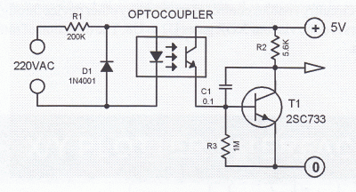
Many microcontroller designs typically integrate various interfacing methods. A microcontroller (µC) system can be viewed as a system that reads from inputs.
Microcontroller systems are versatile platforms that facilitate the integration of multiple interfacing methods to interact with various peripherals and...
Interactive Voice Response System
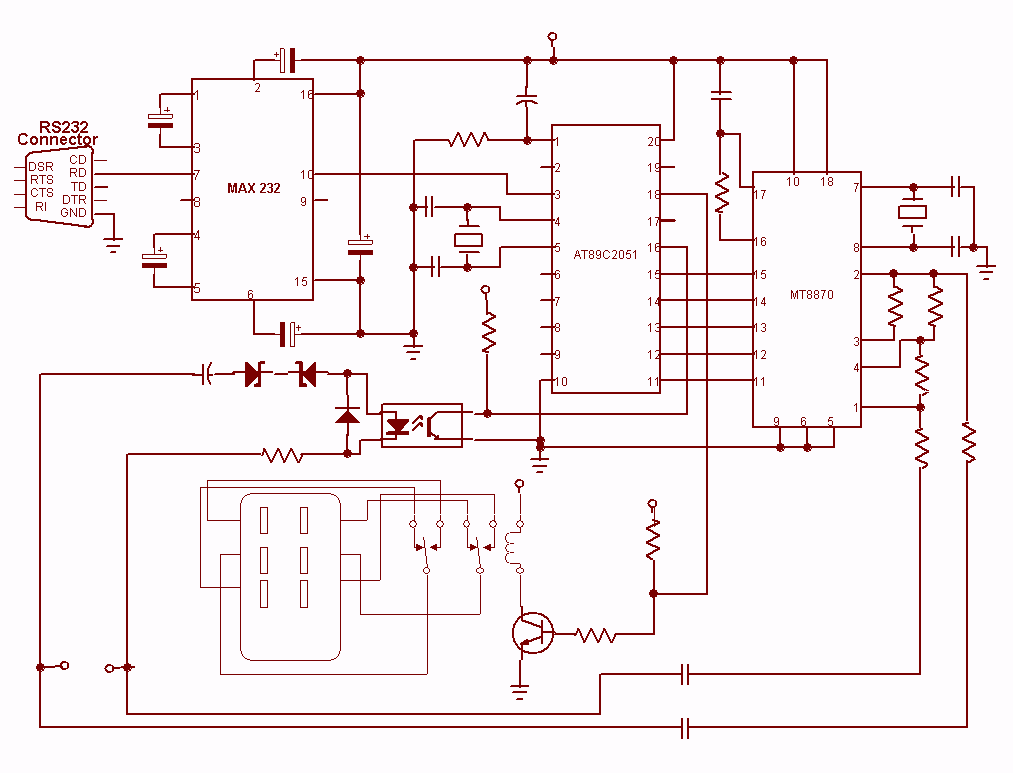
Nowadays every institution needs automation. As a part of college automation, a project has been developed for a Voice Interactive System for College Automation. This project allows users to quickly access student attendance and marks through the telephone line without...
Controlling high-current circuits
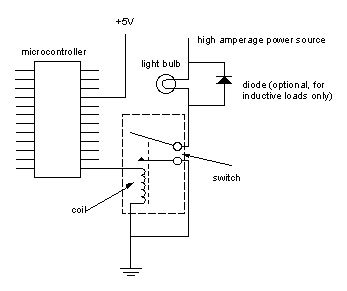
Digital output from a microcontroller is typically a low-amperage signal. For example, when a pin is set HIGH on the microcontroller (in Wiring/Arduino, it is digitalWrite(somePin, HIGH);), the voltage from that pin is usually +3.3V or +5V, with the current...
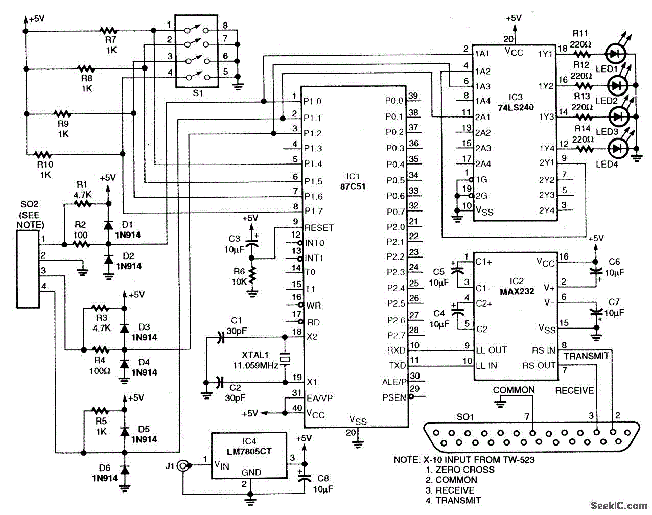
POWER LINE MODEM FOR COMPUTER CONTROL
This circuit employs an 87C57 microcontroller along with several peripherals to convert X-10 power-line carrier-code formats from a personal computer for use with an X-10 power-line interface in a home-control system. Software details can be found in the reference.
The circuit...
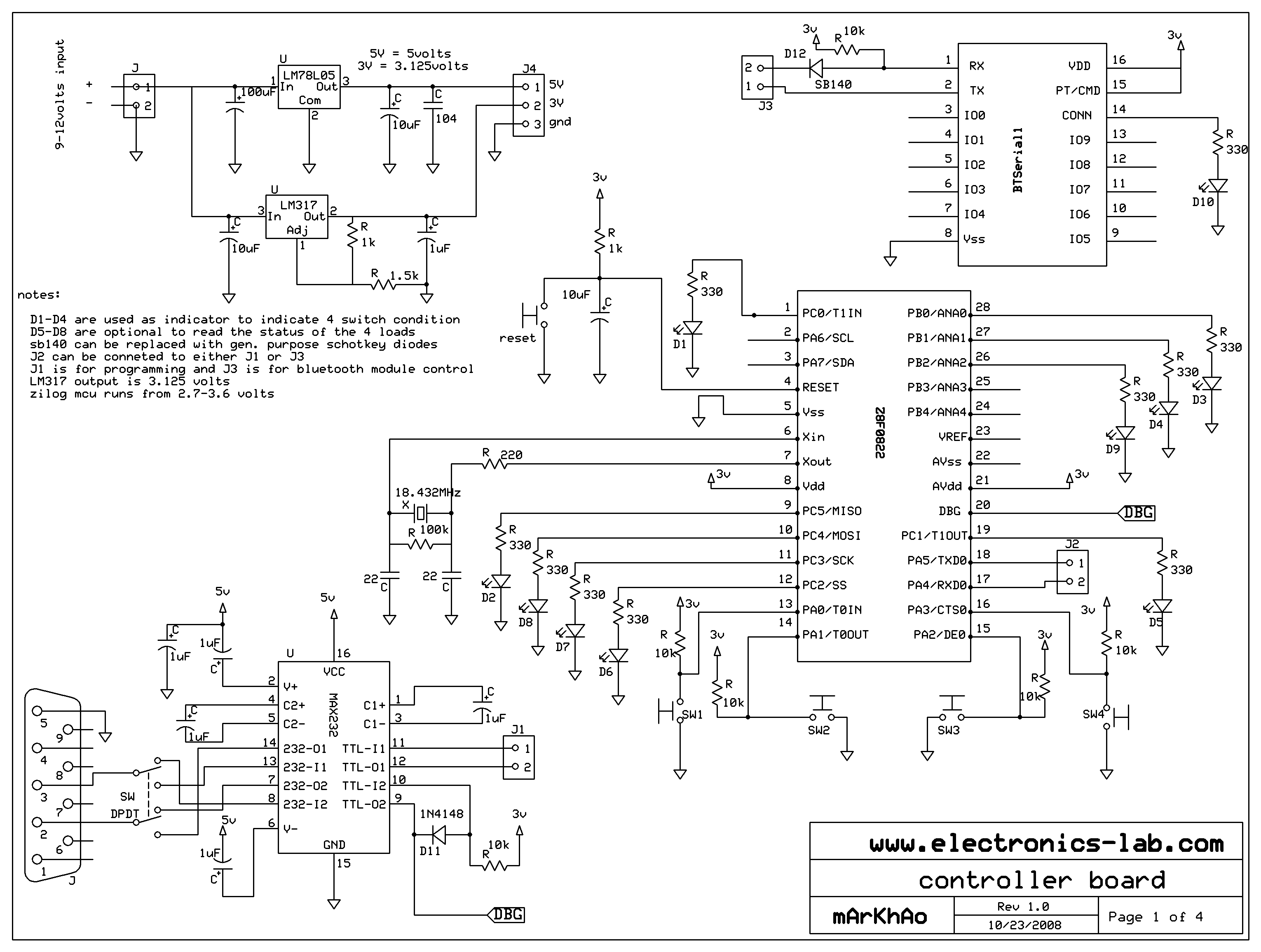
MCU controlled Bluetooth automation
The microcontroller used is 0822 zilog encore! 8k series (soic,28pin) as shown on the figure. Is a programmable microcontroller, the functions used are the GPIO and the UART of the chip. GPIO is used on led indicators, and the UART...
Robot Motor Control Schematic
The schematic for controlling the motors is divided into three main sections, each serving a distinct function. The primary components featured in the schematic include the PIC 18F252 microcontroller, the SN754410 motor driver, and 2N2222 transistors. At the top of...
Jet
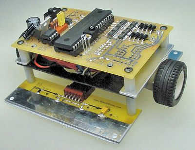
The microcontroller is able to make about 7000 complete line-following decisions per second, which is almost 7 decisions per millimeter when the robot is going full speed. By upping the clock, unrolling loops, and removing my wireless debugging and extraneous...