


Converting an analogue signal to a digital signal
#analogue to digital
#PIC
#signal conversion
#microcontroller
#ADC
#sine wave
#voltage measurement
#low-level signals
#electronics
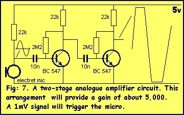
Description: This chapter shows how to connect an analogue signal to a PIC. An analogue signal is similar to a sine wave and is generally less than 5v (5,000mV) in amplitude. Low-level signals are generally expressed in mV, to make them instantly recognisable and easy to talk about.
To connect an analogue signal to a PIC (Peripheral Interface Controller), a suitable interface circuit is required to ensure accurate signal processing and compatibility with the microcontroller's input specifications. The following outlines the essential components and considerations for designing this interface.
1. **Signal Conditioning**: The analogue signal, which may vary in amplitude and frequency, often requires conditioning to fit within the input range of the PIC. This may involve amplification, filtering, and level shifting. An operational amplifier (op-amp) can be used to amplify low-level signals, ensuring they are within the acceptable input range of the PIC's analogue-to-digital converter (ADC).
2. **Voltage Reference**: The PIC typically has a specified reference voltage for its ADC, which is usually set to the maximum input voltage that can be accurately measured. If the analogue signal exceeds the reference voltage, it can lead to saturation and inaccurate readings. A voltage divider can be employed to scale down higher voltage signals to the appropriate level.
3. **Filtering**: To eliminate noise and ensure that only the desired frequency components of the signal are processed, a low-pass filter can be implemented. This filter can be constructed using passive components (resistors and capacitors) or active components (op-amps).
4. **Protection Circuitry**: To protect the PIC from over-voltage situations, it is advisable to include clamping diodes or a transient voltage suppressor. This prevents damage to the microcontroller in cases of unexpected voltage spikes.
5. **Connection to the PIC**: The conditioned analogue signal is then connected to one of the ADC input pins of the PIC. It is vital to ensure that the ground of the signal source is common with the ground of the PIC to avoid ground loop issues, which can introduce errors in the measurements.
6. **Software Configuration**: The PIC's firmware must be configured to read the analogue signal. This involves setting the appropriate ADC channel, configuring the ADC clock, and implementing the necessary code to sample and convert the analogue signal into a digital value for processing.
By carefully designing the interface circuit with these considerations, accurate and reliable analogue signal processing can be achieved, enabling effective interaction between the analogue world and the digital capabilities of the PIC microcontroller.his chapter shows how to connect an analogue signal to a PIC. An analogue signal is similar to a sine wave and is generally less than 5v (5,000mV) in amplitude. Low-level signals are generally expressed in mV, to make them instantly recognisable and easy to talk about.
To connect an analogue signal to a PIC (Peripheral Interface Controller), a suitable interface circuit is required to ensure accurate signal processing and compatibility with the microcontroller's input specifications. The following outlines the essential components and considerations for designing this interface.
1. **Signal Conditioning**: The analogue signal, which may vary in amplitude and frequency, often requires conditioning to fit within the input range of the PIC. This may involve amplification, filtering, and level shifting. An operational amplifier (op-amp) can be used to amplify low-level signals, ensuring they are within the acceptable input range of the PIC's analogue-to-digital converter (ADC).
2. **Voltage Reference**: The PIC typically has a specified reference voltage for its ADC, which is usually set to the maximum input voltage that can be accurately measured. If the analogue signal exceeds the reference voltage, it can lead to saturation and inaccurate readings. A voltage divider can be employed to scale down higher voltage signals to the appropriate level.
3. **Filtering**: To eliminate noise and ensure that only the desired frequency components of the signal are processed, a low-pass filter can be implemented. This filter can be constructed using passive components (resistors and capacitors) or active components (op-amps).
4. **Protection Circuitry**: To protect the PIC from over-voltage situations, it is advisable to include clamping diodes or a transient voltage suppressor. This prevents damage to the microcontroller in cases of unexpected voltage spikes.
5. **Connection to the PIC**: The conditioned analogue signal is then connected to one of the ADC input pins of the PIC. It is vital to ensure that the ground of the signal source is common with the ground of the PIC to avoid ground loop issues, which can introduce errors in the measurements.
6. **Software Configuration**: The PIC's firmware must be configured to read the analogue signal. This involves setting the appropriate ADC channel, configuring the ADC clock, and implementing the necessary code to sample and convert the analogue signal into a digital value for processing.
By carefully designing the interface circuit with these considerations, accurate and reliable analogue signal processing can be achieved, enabling effective interaction between the analogue world and the digital capabilities of the PIC microcontroller.his chapter shows how to connect an analogue signal to a PIC. An analogue signal is similar to a sine wave and is generally less than 5v (5,000mV) in amplitude. Low-level signals are generally expressed in mV, to make them instantly recognisable and easy to talk about.
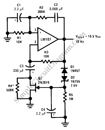
Sine Wave Oscillator
This is a sine wave oscillator circuit, also known as an amplitude-stabilized sine-wave oscillator. It provides a high-purity sine wave output.
This sine wave oscillator circuit is designed to generate a stable sine wave output with minimal distortion, making it suitable...
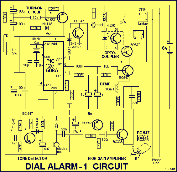
DIAL ALARM-1
This is the lowest cost dialing alarm on the market and shows what can be done with an 8-pin microcontroller. The complete circuit is shown below. You cannot see all the features of this project by looking at the circuit...
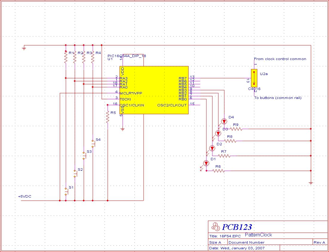
16F54 fickle!
The primary issue observed is that the circuit runs code, but several input/output (I/O) components are non-functional. For instance, only half of the LEDs driven by the circuit operate, and this appears to be random. Attempts to implement the slow...
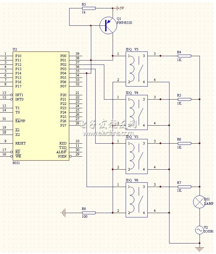
Cipher scheme of the module of infrared remote-control between two parties of intellectual family
This system is a control system based on a single-chip computer that allows for remote operation of lighting. The scheme primarily addresses the transmission and reception of signals, as well as program manipulation of various signals once they are processed...
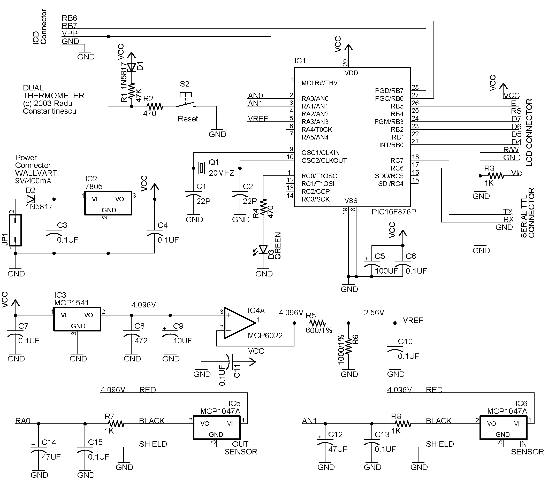
PIC dual Thermometer
This circuit utilizes a PIC16F876 microcontroller, two MCP1047A temperature sensors, an MCP1541 voltage reference, and a MCP6022A operational amplifier. The display is a 2-row HD74780-based 2x16 character display (SII L1652BIJ2), though any HD74780 compatible display can be used. The thermometer,...
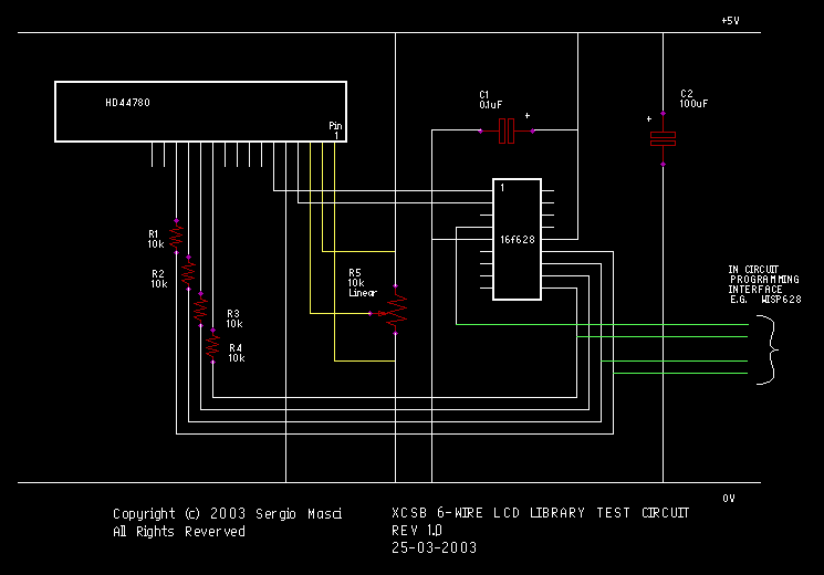
Structured PIC BASIC
This circuit demonstrates the use of the XCSB servo library to control four RC servos. The demo operates on a PIC16F628 microcontroller utilizing the internal 4MHz oscillator. A single push button is employed to select between the servos, while two...
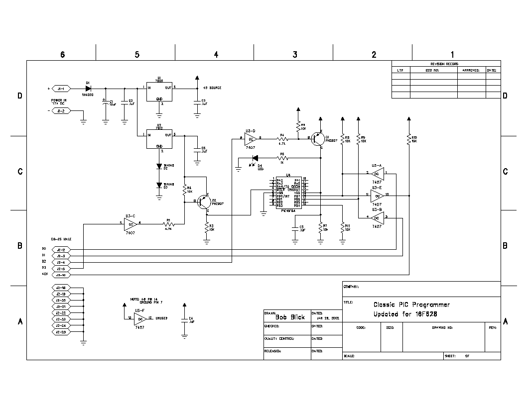
Classic PIC Programmer
This is my own version of the classic PIC 16C84/16F84 programmer. The design is originally by David Tait. I’ve made a few changes, redrawn the schematic and done a board layout. All the files you will need are linked below,...
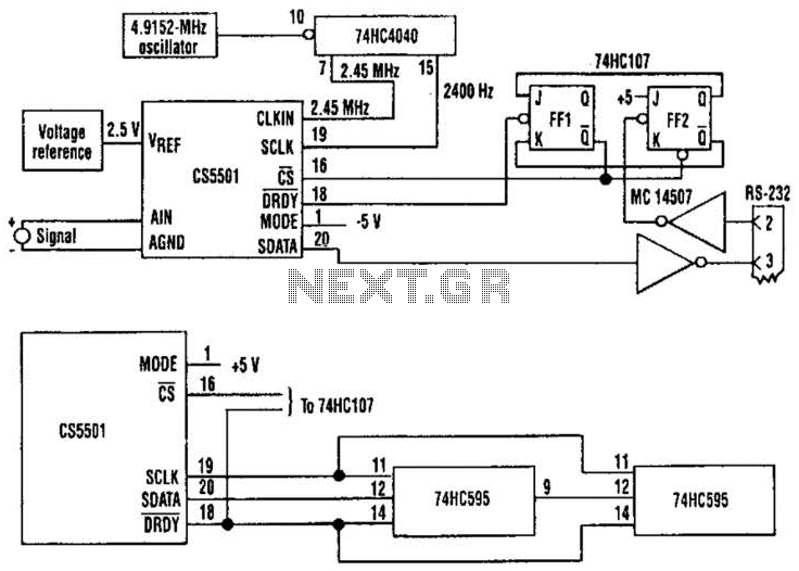
Adc Poller Circuit
The CS5501 16-bit delta-sigma analog-to-digital converter continuously converts signals, outputting conversion words to its output register every 1024 cycles of its master clock, as it lacks a start convert command. By integrating a standard dual J-K flip-flop into the circuit,...
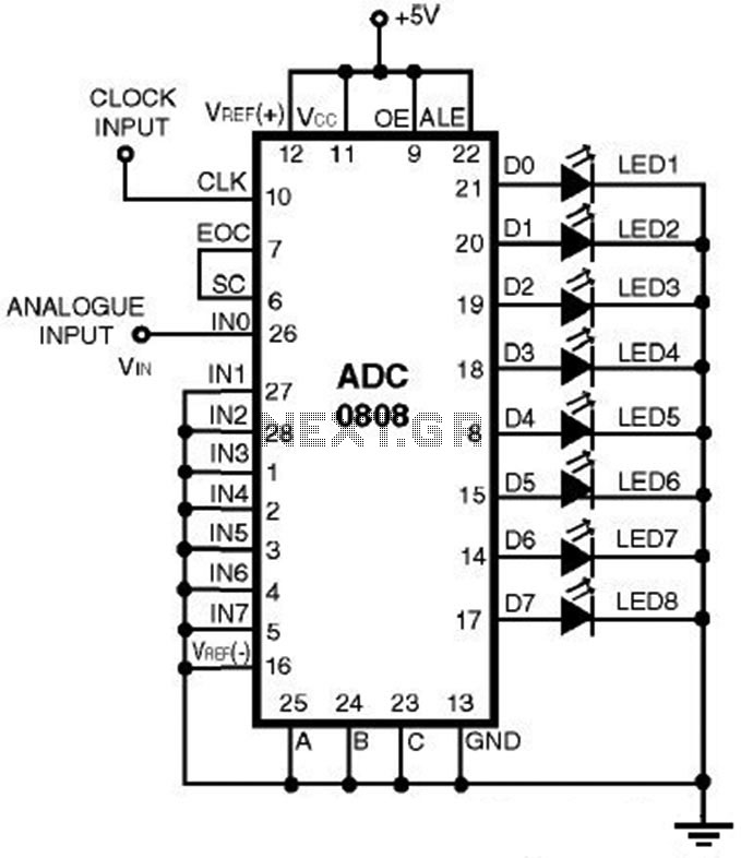
ADC0808 - Simple Analoque to Digital Converter
This is a straightforward analog-to-digital converter circuit utilizing an 8-bit analog-to-digital converter (ADC0808). Typically, an analog-to-digital converter (A/D Converter / ADC) necessitates interfacing with a microprocessor to convert analog signals.
The ADC0808 is a widely used 8-bit A/D converter that can...