


Digital switch for your camera
#camera switch
#digital switch
#microcontroller
#photography
#electronics
#DIY
#camera control
#arduino
#raspberry pi
#sensor
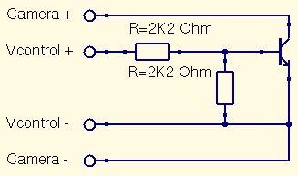
Description: This is a straightforward guide to constructing a digital switch for a camera, enabling photo capture through microcontrollers. Required components include: 1.
A digital switch for a camera can be implemented using a microcontroller, such as an Arduino or Raspberry Pi, along with a few additional electronic components. The primary function of this circuit is to control the camera's shutter release, allowing for automated photography.
The basic components required for this project include a microcontroller, a transistor or relay to act as a switch, a resistor, and connecting wires. The microcontroller will be programmed to send a signal to the transistor or relay, which will then close the circuit and trigger the camera's shutter.
The circuit can be laid out as follows:
1. **Microcontroller**: The microcontroller serves as the brain of the operation. It should be programmed to send a digital signal at specified intervals or in response to specific conditions, such as a sensor input.
2. **Transistor/Relay**: A transistor can be used to switch the camera's shutter. When the microcontroller outputs a HIGH signal, the transistor allows current to flow, simulating a button press on the camera. Alternatively, a relay can be used for higher current applications, providing electrical isolation between the microcontroller and the camera.
3. **Resistor**: A resistor is typically placed in series with the base of the transistor to limit the current flowing into it, ensuring that the transistor operates within safe limits.
4. **Power Supply**: Ensure that the circuit is powered appropriately. The microcontroller should be powered via USB or a suitable battery, while the camera may require its own power source depending on the design.
5. **Connections**: The shutter release cable of the camera should be connected to the collector of the transistor or the relay's normally open contact. The emitter of the transistor should be connected to ground, while the base is connected to a digital output pin of the microcontroller through the resistor.
By utilizing this setup, users can automate the photography process, allowing for time-lapse photography, remote shooting, and other creative applications. Proper programming and testing are essential to ensure reliable operation and to avoid any potential damage to the camera.This is a very easy instructable to build a digital switch for your camera in order to take photos with your microcontrollers. What you need: 1..
A digital switch for a camera can be implemented using a microcontroller, such as an Arduino or Raspberry Pi, along with a few additional electronic components. The primary function of this circuit is to control the camera's shutter release, allowing for automated photography.
The basic components required for this project include a microcontroller, a transistor or relay to act as a switch, a resistor, and connecting wires. The microcontroller will be programmed to send a signal to the transistor or relay, which will then close the circuit and trigger the camera's shutter.
The circuit can be laid out as follows:
1. **Microcontroller**: The microcontroller serves as the brain of the operation. It should be programmed to send a digital signal at specified intervals or in response to specific conditions, such as a sensor input.
2. **Transistor/Relay**: A transistor can be used to switch the camera's shutter. When the microcontroller outputs a HIGH signal, the transistor allows current to flow, simulating a button press on the camera. Alternatively, a relay can be used for higher current applications, providing electrical isolation between the microcontroller and the camera.
3. **Resistor**: A resistor is typically placed in series with the base of the transistor to limit the current flowing into it, ensuring that the transistor operates within safe limits.
4. **Power Supply**: Ensure that the circuit is powered appropriately. The microcontroller should be powered via USB or a suitable battery, while the camera may require its own power source depending on the design.
5. **Connections**: The shutter release cable of the camera should be connected to the collector of the transistor or the relay's normally open contact. The emitter of the transistor should be connected to ground, while the base is connected to a digital output pin of the microcontroller through the resistor.
By utilizing this setup, users can automate the photography process, allowing for time-lapse photography, remote shooting, and other creative applications. Proper programming and testing are essential to ensure reliable operation and to avoid any potential damage to the camera.This is a very easy instructable to build a digital switch for your camera in order to take photos with your microcontrollers. What you need: 1..
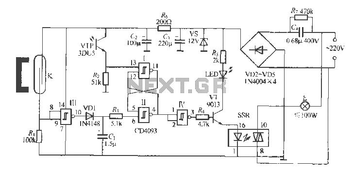
Gate automatic lamp circuit
The circuit utilizes multiple integrated circuits to form an automatic lighting device that is activated by door and window sensors. It includes CD4093 digital integrated circuits, a relay, and a power supply circuit. The system typically remains closed when a...
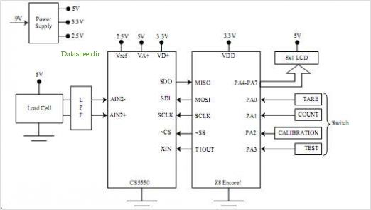
High Resolution Digital Weigh-scale Design Using Z8 Encore! ?® Microcontrollers
The SP6691 circuit is designed to provide a high output voltage using a lower voltage boost regulator by incorporating a charge pump circuit. This configuration can convert a standard 30V boost regulator into a 60V boost regulator if necessary. Testing...
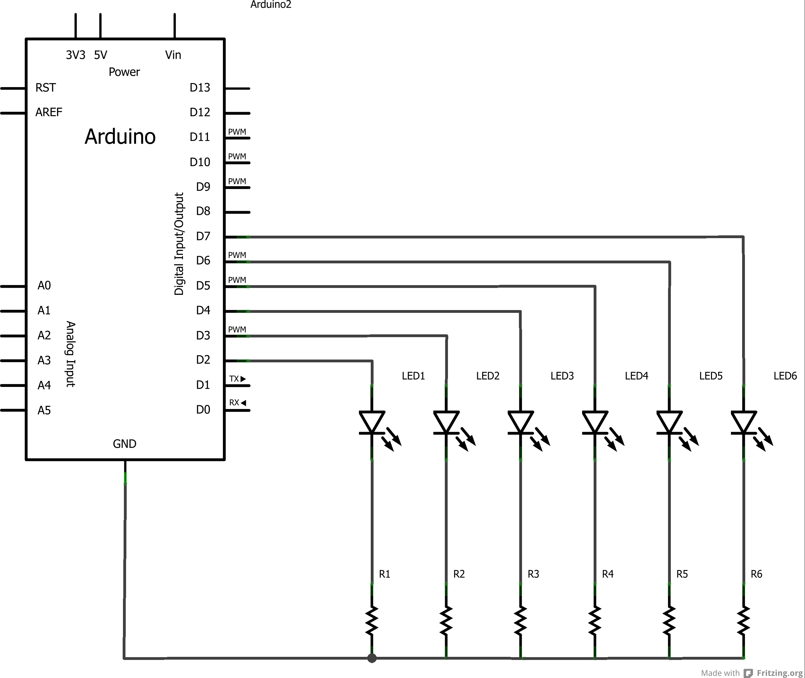
arduino masterpieces
A challenge encountered when beginning to work with Arduino was determining how to create circuit diagrams for projects. There are numerous software options available for drawing schematic diagrams, some of which are free while others require payment, each presenting a...
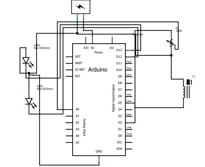
Small Engine ECU EFI Moped Using Ardrino UNO
After several days of considering electronic fuel injection for a moped, a decision has been made to proceed with the project. The required parts have been identified, and the remaining task involves programming.
The implementation of electronic fuel injection (EFI) in...
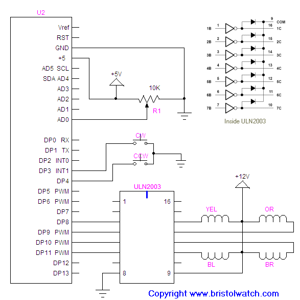
arduino unipolar stepper
How to connect and program the Arduino/Atmega168 microcontroller to operate a unipolar stepper motor.
To connect and program the Arduino/Atmega168 microcontroller for operating a unipolar stepper motor, the following steps should be followed:
1. **Components Required**:
- Arduino or Atmega168...
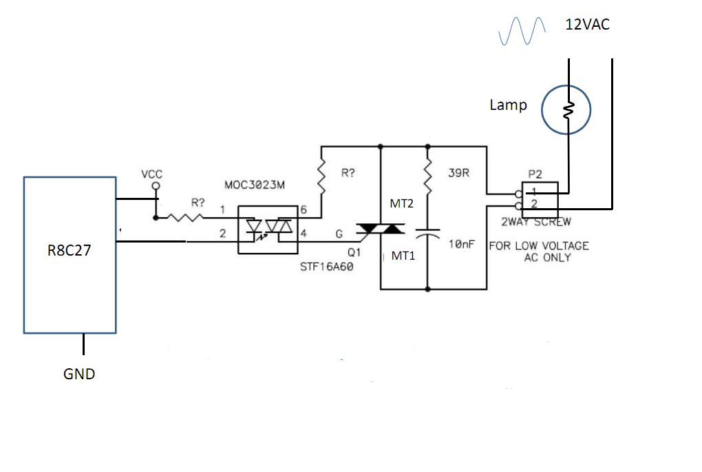
What kind of transistor do I need to amplify an Arduinos PWM outputs
Control 30 incandescent light bulbs with an Arduino Uno on three channels (10 bulbs per channel in parallel). Previous experience involved using an Arduino to control red, green, and blue LEDs with a simple schematic that included three transistors. However,...
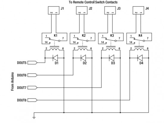
Appliance Remote Control Arduino Project
Starting today, interesting Arduino projects from various sources will be shared. The author is a novice in this field but is committed to understanding it fully. It should be noted that the projects are not developed by the author, and...
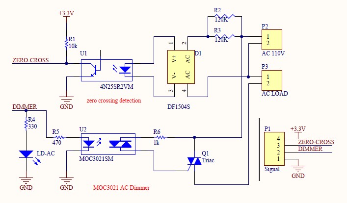
microcontroller Arduino 230v Light bulb dimming
Have you verified whether you can see the zero crossings on your input pin? It may be beneficial to write a sketch that toggles the LED on pin 13 every 50 or 60 zero crossings. This should result in a...
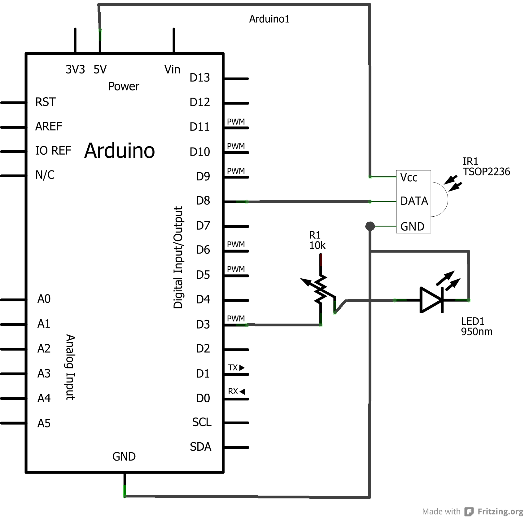
Arduino based electricity meter
The concept involves using infrared light that is reflected by a disc, except for a dark red line. The sensor receives the reflected light, allowing the Arduino to track the number of revolutions. The infrared sensor is tuned to a...