


Dragon12
#Dragon12
#microcontroller
#Rev. C
#Rev. D
#schematics
#hardware
#getting started
#board revision
#manual

Description: Manuals and schematics for the Rev. C and D boards are provided below. The board revision number can be found on the lower right-hand side of the board near the edge. The Rev. C schematics are very similar to those of Rev. D; therefore, only the Rev. C schematics are included. The "Dragon12 Getting Started" manual (Rev. D) covers the fundamentals of the Dragon12 board hardware and programming, and it is applicable to the Rev. C board as well. Additionally, manuals and schematics for the newer Rev. E boards are also listed below. The Rev. E board is quite similar to the Rev. C/D boards, but it is essential to program Port J1 (PJ1/pin 21 of the DP256) as an output and set it to logic 0 (low) for the Port B LEDs to illuminate. Programs that utilize the Port B LEDs on the Rev. E will function correctly on the Rev. C/D boards, but the reverse is not true. The "Dragon12 Getting Started Manual" (Rev. E) covers the basics of the Dragon12 board hardware and programming.
The Dragon12 board series, including Rev. C, D, and E, serves as a versatile platform for embedded systems design, offering a range of functionalities suitable for educational and practical applications. The schematics and manuals provided for these revisions are crucial for understanding the hardware layout and programming techniques necessary for effective use.
The Rev. C schematics detail the connections and components utilized within the board, including power distribution, microcontroller pin assignments, and peripheral interfaces. The microcontroller used in these boards is the DP256, which supports various I/O operations, making it suitable for a wide range of applications. The documentation emphasizes the importance of correctly configuring the I/O ports, particularly Port J1, which must be programmed as an output to control the Port B LEDs effectively.
The Rev. E board introduces minor enhancements over its predecessors, maintaining compatibility while requiring specific programming adjustments to function optimally. The documentation for Rev. E highlights the need for setting Port J1 to a low logic state to activate the LEDs on Port B, ensuring that users are aware of the differences in operation between the revisions.
Overall, the Dragon12 boards represent a comprehensive resource for those engaged in embedded systems projects, providing essential information through detailed manuals and schematics that facilitate learning and application of programming and hardware integration.Manuals/Schematics for the Rev. C and D boards are listed just below. You can see the board revision number on the lower right hand side of the board near the edge. The Rev. C schematics are very close to the Rev. D schematics, so only the Rev. C schematics are listed. Dragon12_getting_started. pdf - Covers the basics of the Dragon12 board hardwar e (rev. D) and programming (pdf, 15 pages, 84 kB). Works OK for the Rev. C board as well. - Manuals/Schematics for the newer Rev. E boards are listed just below (you can see the board revision number on the lower right hand side of the board near the edge). Note that the Rev. E board is very similar to the Rev. C/D boards, but you must program Port J1 (PJ1/ pin 21 of the DP256) as an output and set it to logic 0 (low) in order for the Port B LEDs to light.
Programs that use the port B LEDs on Rev. E will work OK on Rev. C/D boards, but not vice versa. Welcome to the real world of embedded systems design. * Dragon12 Getting Started Manual (Rev. E) Dragon12_getting_started_revE. pdf - Covers the basics of the Dragon12 board hardware (rev. E) and programming (pdf, 19 pages, 128 kB).
The Dragon12 board series, including Rev. C, D, and E, serves as a versatile platform for embedded systems design, offering a range of functionalities suitable for educational and practical applications. The schematics and manuals provided for these revisions are crucial for understanding the hardware layout and programming techniques necessary for effective use.
The Rev. C schematics detail the connections and components utilized within the board, including power distribution, microcontroller pin assignments, and peripheral interfaces. The microcontroller used in these boards is the DP256, which supports various I/O operations, making it suitable for a wide range of applications. The documentation emphasizes the importance of correctly configuring the I/O ports, particularly Port J1, which must be programmed as an output to control the Port B LEDs effectively.
The Rev. E board introduces minor enhancements over its predecessors, maintaining compatibility while requiring specific programming adjustments to function optimally. The documentation for Rev. E highlights the need for setting Port J1 to a low logic state to activate the LEDs on Port B, ensuring that users are aware of the differences in operation between the revisions.
Overall, the Dragon12 boards represent a comprehensive resource for those engaged in embedded systems projects, providing essential information through detailed manuals and schematics that facilitate learning and application of programming and hardware integration.Manuals/Schematics for the Rev. C and D boards are listed just below. You can see the board revision number on the lower right hand side of the board near the edge. The Rev. C schematics are very close to the Rev. D schematics, so only the Rev. C schematics are listed. Dragon12_getting_started. pdf - Covers the basics of the Dragon12 board hardwar e (rev. D) and programming (pdf, 15 pages, 84 kB). Works OK for the Rev. C board as well. - Manuals/Schematics for the newer Rev. E boards are listed just below (you can see the board revision number on the lower right hand side of the board near the edge). Note that the Rev. E board is very similar to the Rev. C/D boards, but you must program Port J1 (PJ1/ pin 21 of the DP256) as an output and set it to logic 0 (low) in order for the Port B LEDs to light.
Programs that use the port B LEDs on Rev. E will work OK on Rev. C/D boards, but not vice versa. Welcome to the real world of embedded systems design. * Dragon12 Getting Started Manual (Rev. E) Dragon12_getting_started_revE. pdf - Covers the basics of the Dragon12 board hardware (rev. E) and programming (pdf, 19 pages, 128 kB).
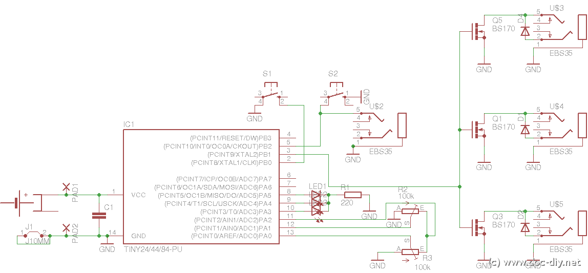
delay
This article outlines the construction of a simple microcontroller-based delay circuit designed for photographic applications, such as drop or high-speed photography. It is capable of controlling the trigger lag for cameras and flash units, generating periodic trigger pulses, or managing...
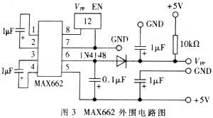
The embedded microcontroller MC68HC912B32 background debugs the mode to design
The widespread application of Flash technology in microprocessors has led to significant advancements in the development and utilization of one-chip computers. Designers have transitioned from traditional in-circuit emulators (ICE) and JTAG interfaces to more cost-effective and user-friendly development methods. While...
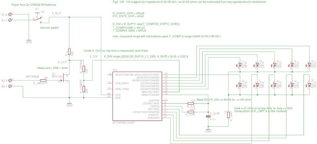
Microcontroller interface electrometer
A method for measuring static electricity for a science project was sought. An old copy of "Getting Started in Electronics" by Forrest M. Mims III was referenced for guidance.
To create a static electricity measurement circuit, a simple design can be...
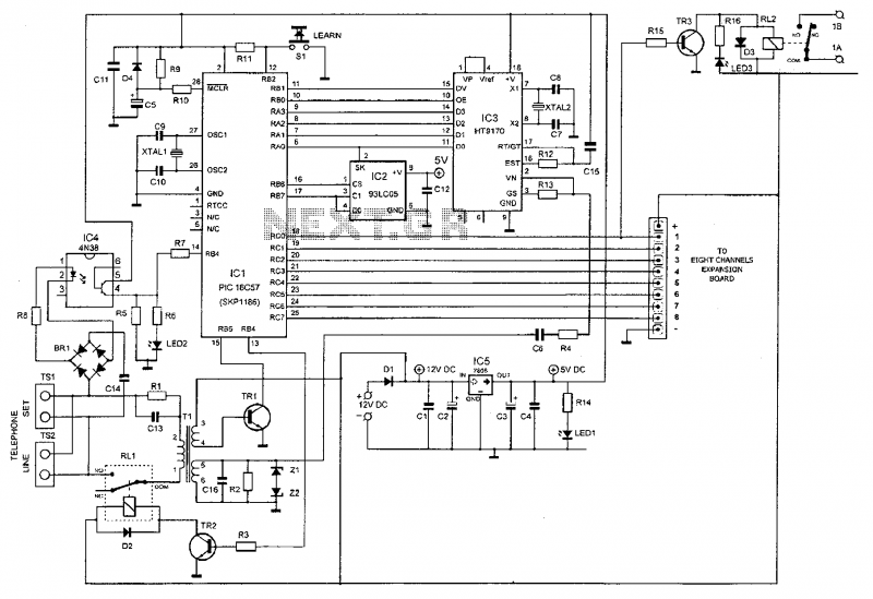
Microcontroller Based Telephone Remote Control Circuit
This device enables remote control of various appliances (up to eight with suitable add-on expansion boards) such as lights, water heaters, air conditioning, plant watering systems, alarms, etc., via a relay. It allows users to perform actions such as watering...
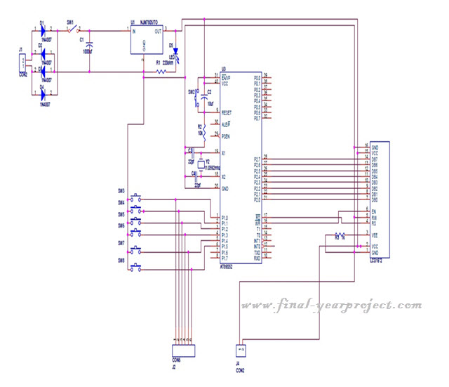
Microcontroller based College Automation System
This project is a microcontroller-based college automation system aimed at addressing the challenges faced in educational institutions. It replaces the conventional notice board with an automated device that allows users to both hear and read the information being announced through...
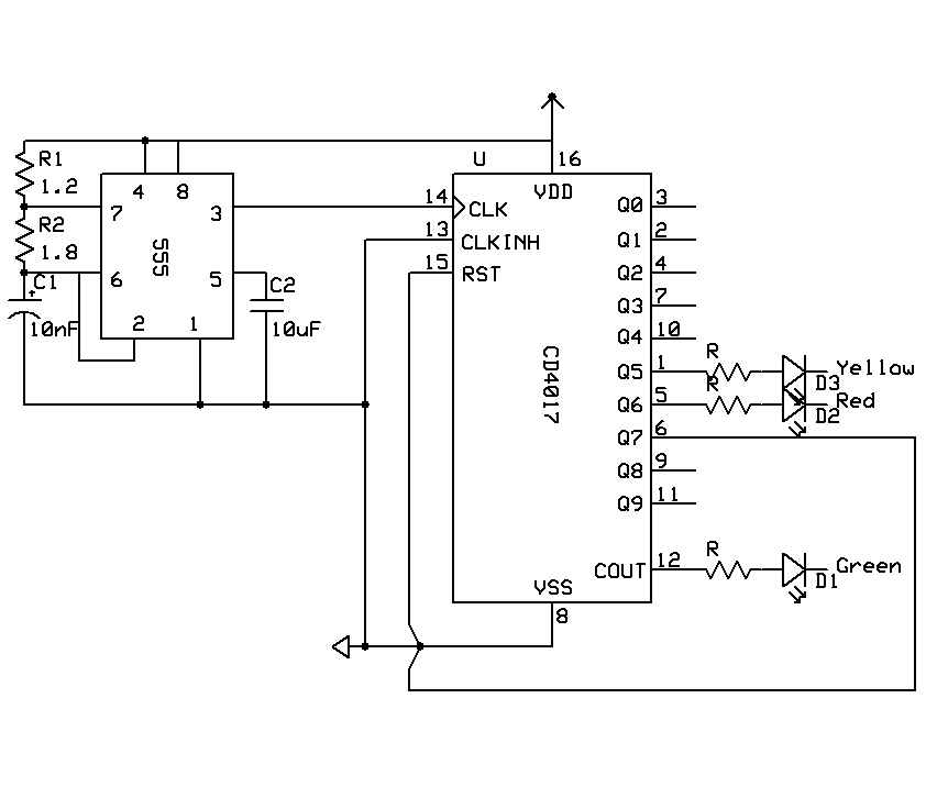
Training Boxing timer schematic
A timer is being developed for circuit training or boxing training. The timer does not require any external input, except for a reset function. The project can be simplified using a microcontroller, such as the PIC12F635, which is cost-effective at...
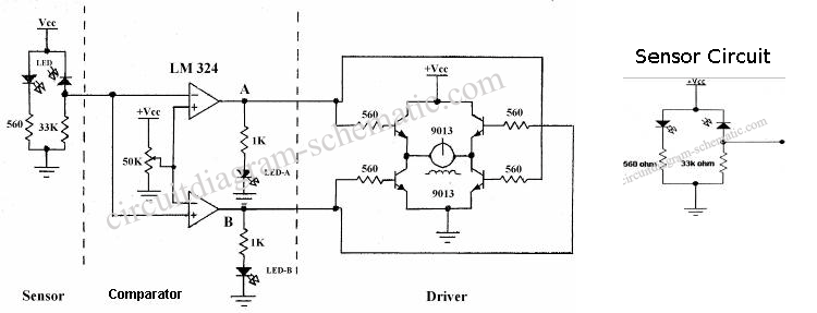
Sensor Circuit Of Analog Line Follower Robot
The following circuit illustrates the sensor circuit of an analog line follower robot. Features include control by a microcontroller and a sensor circuit.
The sensor circuit for an analog line follower robot is designed to detect the presence of a line...
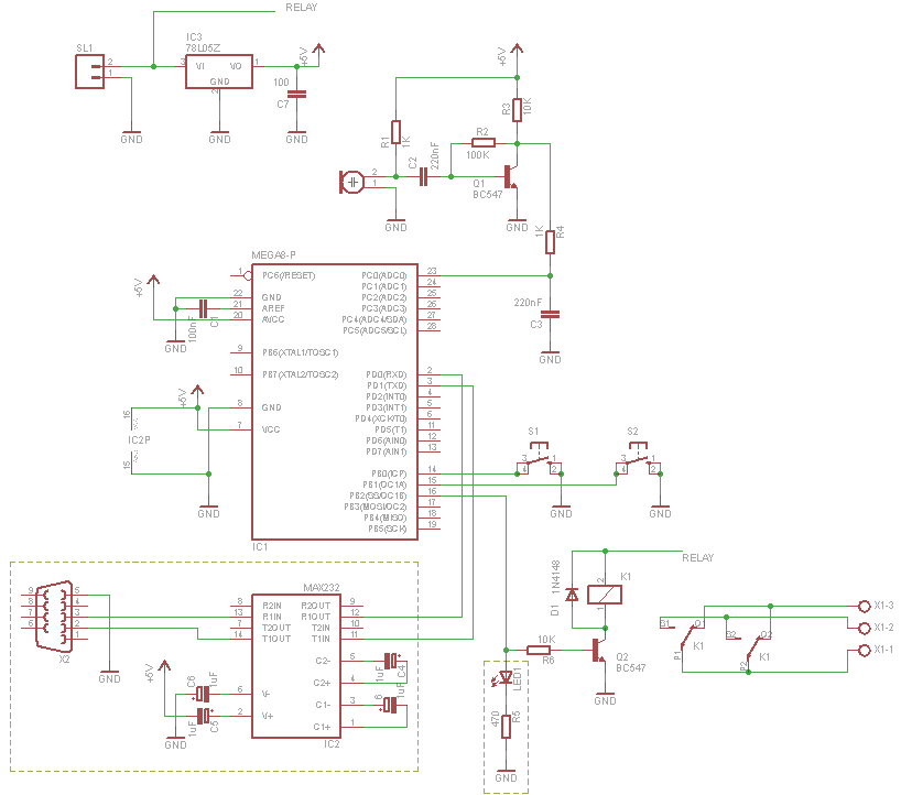
Microcontroller Clapper Switch
For those who prefer convenience, it is possible to turn the bedroom light on or off without leaving the bed simply by clapping hands. This concept inspired the design of a clap-activated light control system. Various clap switch projects can...
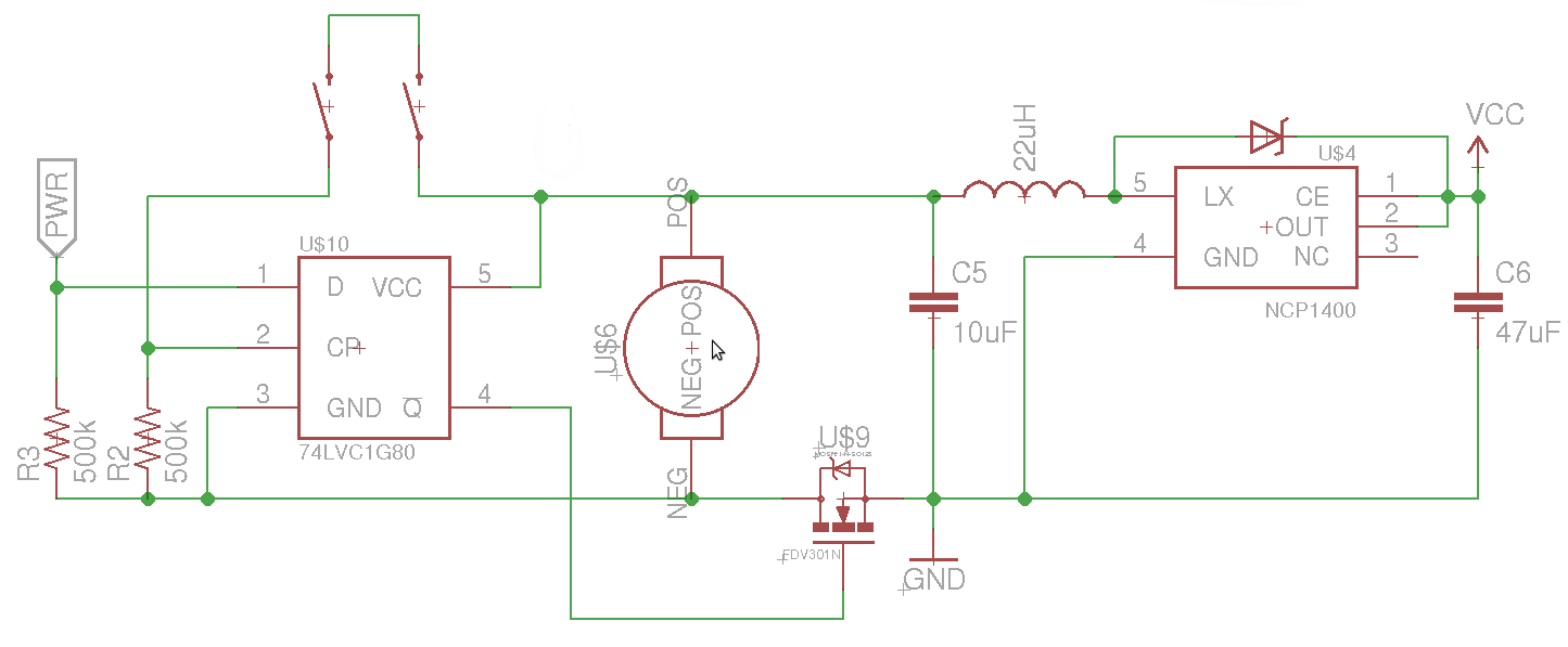
mosfet Turning a microcontroller on with a flip flop
The objective is to control the power to a load, specifically an 8051-based microcontroller (uC), using two switches. When the uC is powered on, it sets the PWR pin high. Upon pressing the switches again, pin 4 of the flip-flop...