


Fluke 8010 / 8012
#Fluke 8010
#Fluke 8012
#CCU3000
#Intermetall
#Micronas
#microcontroller circuit
#interface diagram
#embedded systems
Description: The Fluke interface diagram illustrates a typical microcontroller circuit centered around the CCU3000 microcontroller from Intermetall/Micronas. While the diagram may appear simplistic, it encapsulates essential functionalities. The CCU3000 microcontroller is selected for its ample I/O lines, floating input pins, and low current consumption, critical due to the limited power supply of the Fluke 8010/8012. Operating at 1 MHz, the circuit's total current consumption is approximately 3 mA. The CCU3000 utilizes a 4 MHz crystal oscillator connected between pins 3 and 4, with an internal frequency division factor of 4 to achieve a 1 MHz clock suitable for the application. A straightforward reset circuit comprising an RC network connected to pin 6 ensures reliable operation, with a diode across the resistor for rapid capacitor discharge during power failures. Pin 17 must be pulled high with a resistor to enable the CCU3000 to retrieve its mode control byte from external memory, as it lacks internal memory. An EPROM with a capacity of 32 kb is utilized, although the program only occupies about 6 kb. The EPROM's OE line is grounded, keeping it active, while the CCU3000 ignores the address bus when accessing internal memory or I/O peripherals. The power supply features the LM2936-5 linear regulator, known for its low quiescent current, contributing to overall low power consumption. Decoupling capacitors of at least 22 µF are essential for stable operation. The X24C02 serves as an I²C-controlled non-volatile memory (NVM) with a capacity of 256 bytes, although a larger option, such as the X24C16, could be used. The NVM stores minimal data, including the SB-Bus address and meter model. The SB-Bus connection in the diagram includes two opto-couplers for galvanic insulation between the SB-Bus and the meter.
The schematic design of the Fluke interface highlights a microcontroller-based system designed for efficient operation in a compact environment. The CCU3000 microcontroller serves as the core processing unit, facilitating input and output operations through its numerous I/O lines. The choice of using floating input pins is significant, as it allows for flexibility in interfacing with various sensors and devices without the need for pull-up or pull-down resistors, simplifying the overall design.
The clock system is critical for timing operations within the microcontroller. The 4 MHz crystal oscillator provides a stable frequency reference, which is internally divided to achieve a lower clock speed of 1 MHz. This reduction not only meets the timing requirements of the application but also minimizes power consumption, a vital consideration for battery-operated devices.
The reset circuit's simplicity is noteworthy; it employs a resistor-capacitor (RC) network to ensure the microcontroller resets correctly upon power-up or when voltage levels fluctuate. The inclusion of a diode enhances reliability by ensuring rapid discharge of the capacitor, thereby preventing erroneous operation during brief power interruptions.
Memory management is efficiently handled through the use of an external EPROM. The decision to use a 32 kb EPROM, despite the program's modest size of 6 kb, is justified by the availability of components and their low power characteristics. Grounding the OE line ensures that the EPROM remains active, allowing seamless data retrieval without additional control logic.
The power supply design incorporates the LM2936-5 linear regulator, selected for its low quiescent current. This choice is critical in maintaining the overall power efficiency of the circuit. The requirement for decoupling capacitors emphasizes the importance of stable voltage levels, preventing potential oscillations that could disrupt operation.
The integration of the X24C02 I²C-controlled NVM provides a simple yet effective solution for storing configuration data, such as the SB-Bus address. The use of opto-couplers for galvanic isolation is a prudent design decision, ensuring that the microcontroller and the external SB-Bus interface operate independently, thus enhancing the system's reliability and safety.
Overall, the Fluke interface diagram represents a well-thought-out microcontroller circuit, balancing performance, power efficiency, and simplicity in design, making it an exemplary model for similar applications in electronic engineering.The Fluke interface diagram is an example of a typical microcontroller circuit. There is not really much to see, apart from the microcontroller itself. Nevertheless I`ll try to explain what`s happening here, because not everything is as obvious as it may seem at first glance. I chose the CCU3000 microcontroller from Intermetall/Micronas for this p roject for a few important reasons. First of all it has more than the required number of I/O lines. All the input pins are really floating, which is also one of the requirements (I`ll explain why later). And last, but not least, it has a quite modest current consumption, which is important because the power supply of the Fluke 8010/8012 is quite small and may not be loaded to heavily.
By running the CCU3000 at 1MHz I could reduce the current consumption of the total circuit down to about 3 mA. The CCU3000 operates on a 4 MHz crystal oscillator, which is connected between the pins 3 and 4. Internally this frequency can be divided down to an appropriate value. I chose a division factor of 4 to reduce the power consumption, resulting in an internal clock frequency of 1 MHz, which is more than sufficient for our application.
The reset circuit is also an example of simplicity. A simple RC network connected to pin 6 will do the trick. A diode is added across the resistor to achieve a fast discharge of the capacitor when the power fails, which will guarantee a proper restart if the power supply is interrupted only briefly. The diode will start conducting as soon as the power supply voltage drops below the charge level of the capacitor, effectively discharging the capacitor.
It is important to pull pin 17 high with a resistor to make the CCU3000 fetch its mode control byte from external memory, for there is no internal memory to fetch it from. I do admit that the EPROM is a bit over sized with its 32 kb, for the program is just about 6 kb long.
I had ample 32kb EEPROMs in stock, and they are almost always made in CMOS technology, which is a requirement ta achieve low power consumption. It is hardly possible to reveal any more secrets about the connection of the EPROM in this circuit. Except that the OE line of the device is permanently tied to ground, making it active all the time. This is no problem because the EPROM is the only device connected externally to the address/data bus of the CCU3000.
The address bus is ignored by the CCU3000 when addressing internal memory or I/O peripherals. Again nothing special here. The power supply consist mainly of the linear regulator LM2936-5, which excels in a very low quiescent current which also contributes to the low overall power consumption. You may also use a normal 78L05 if you can`t get the LM2936-5, at the expense of a slightly increased consumption.
It is very important to de-couple the input and the output of the LM2936-5 with capacitors of at least 22 µF, otherwise you risk a heavily oscillating power supply! It goes without saying that the connection between these capacitors to the LM2936-5 must be as short as possible.
The X24C02 is an I ²C controlled NVM, with a data capacity of 256 bytes. Many different manufacturers exist on the NVM market, so there should be plenty compatible ICs to choose from. It is even possible to put in a larger memory, eg the X24C16. This little EEPROM is a bit over sized for it has only 2 things to remember, the SB-Bus address and the meter model.
The SB-Address is only 7 bits wide, and the meter model can be represented by only 1 bit. I`ve added 2 identification bytes to verify the validity of the data, which adds up to a total of 3 bytes used of the available 256. The SB-Bus connection shown in the upper right hand corner of the diagram shows all that is needed to make the interface connect to the outside world.
The two opto-couplers take care of the necessary galvanic insulation between the SB-Bus and the meter. Please bear in mind that the ground
The schematic design of the Fluke interface highlights a microcontroller-based system designed for efficient operation in a compact environment. The CCU3000 microcontroller serves as the core processing unit, facilitating input and output operations through its numerous I/O lines. The choice of using floating input pins is significant, as it allows for flexibility in interfacing with various sensors and devices without the need for pull-up or pull-down resistors, simplifying the overall design.
The clock system is critical for timing operations within the microcontroller. The 4 MHz crystal oscillator provides a stable frequency reference, which is internally divided to achieve a lower clock speed of 1 MHz. This reduction not only meets the timing requirements of the application but also minimizes power consumption, a vital consideration for battery-operated devices.
The reset circuit's simplicity is noteworthy; it employs a resistor-capacitor (RC) network to ensure the microcontroller resets correctly upon power-up or when voltage levels fluctuate. The inclusion of a diode enhances reliability by ensuring rapid discharge of the capacitor, thereby preventing erroneous operation during brief power interruptions.
Memory management is efficiently handled through the use of an external EPROM. The decision to use a 32 kb EPROM, despite the program's modest size of 6 kb, is justified by the availability of components and their low power characteristics. Grounding the OE line ensures that the EPROM remains active, allowing seamless data retrieval without additional control logic.
The power supply design incorporates the LM2936-5 linear regulator, selected for its low quiescent current. This choice is critical in maintaining the overall power efficiency of the circuit. The requirement for decoupling capacitors emphasizes the importance of stable voltage levels, preventing potential oscillations that could disrupt operation.
The integration of the X24C02 I²C-controlled NVM provides a simple yet effective solution for storing configuration data, such as the SB-Bus address. The use of opto-couplers for galvanic isolation is a prudent design decision, ensuring that the microcontroller and the external SB-Bus interface operate independently, thus enhancing the system's reliability and safety.
Overall, the Fluke interface diagram represents a well-thought-out microcontroller circuit, balancing performance, power efficiency, and simplicity in design, making it an exemplary model for similar applications in electronic engineering.The Fluke interface diagram is an example of a typical microcontroller circuit. There is not really much to see, apart from the microcontroller itself. Nevertheless I`ll try to explain what`s happening here, because not everything is as obvious as it may seem at first glance. I chose the CCU3000 microcontroller from Intermetall/Micronas for this p roject for a few important reasons. First of all it has more than the required number of I/O lines. All the input pins are really floating, which is also one of the requirements (I`ll explain why later). And last, but not least, it has a quite modest current consumption, which is important because the power supply of the Fluke 8010/8012 is quite small and may not be loaded to heavily.
By running the CCU3000 at 1MHz I could reduce the current consumption of the total circuit down to about 3 mA. The CCU3000 operates on a 4 MHz crystal oscillator, which is connected between the pins 3 and 4. Internally this frequency can be divided down to an appropriate value. I chose a division factor of 4 to reduce the power consumption, resulting in an internal clock frequency of 1 MHz, which is more than sufficient for our application.
The reset circuit is also an example of simplicity. A simple RC network connected to pin 6 will do the trick. A diode is added across the resistor to achieve a fast discharge of the capacitor when the power fails, which will guarantee a proper restart if the power supply is interrupted only briefly. The diode will start conducting as soon as the power supply voltage drops below the charge level of the capacitor, effectively discharging the capacitor.
It is important to pull pin 17 high with a resistor to make the CCU3000 fetch its mode control byte from external memory, for there is no internal memory to fetch it from. I do admit that the EPROM is a bit over sized with its 32 kb, for the program is just about 6 kb long.
I had ample 32kb EEPROMs in stock, and they are almost always made in CMOS technology, which is a requirement ta achieve low power consumption. It is hardly possible to reveal any more secrets about the connection of the EPROM in this circuit. Except that the OE line of the device is permanently tied to ground, making it active all the time. This is no problem because the EPROM is the only device connected externally to the address/data bus of the CCU3000.
The address bus is ignored by the CCU3000 when addressing internal memory or I/O peripherals. Again nothing special here. The power supply consist mainly of the linear regulator LM2936-5, which excels in a very low quiescent current which also contributes to the low overall power consumption. You may also use a normal 78L05 if you can`t get the LM2936-5, at the expense of a slightly increased consumption.
It is very important to de-couple the input and the output of the LM2936-5 with capacitors of at least 22 µF, otherwise you risk a heavily oscillating power supply! It goes without saying that the connection between these capacitors to the LM2936-5 must be as short as possible.
The X24C02 is an I ²C controlled NVM, with a data capacity of 256 bytes. Many different manufacturers exist on the NVM market, so there should be plenty compatible ICs to choose from. It is even possible to put in a larger memory, eg the X24C16. This little EEPROM is a bit over sized for it has only 2 things to remember, the SB-Bus address and the meter model.
The SB-Address is only 7 bits wide, and the meter model can be represented by only 1 bit. I`ve added 2 identification bytes to verify the validity of the data, which adds up to a total of 3 bytes used of the available 256. The SB-Bus connection shown in the upper right hand corner of the diagram shows all that is needed to make the interface connect to the outside world.
The two opto-couplers take care of the necessary galvanic insulation between the SB-Bus and the meter. Please bear in mind that the ground
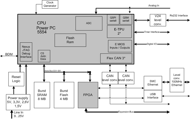
Electronics Engineering Herald - online magazine of electronics -home
Embedded systems serve as the core of most electronics-based systems, enabling data access, processing, storage, and control. While some simple electronic circuits can be designed without a microprocessor or microcontroller, this approach is often economically impractical, except for basic passive...
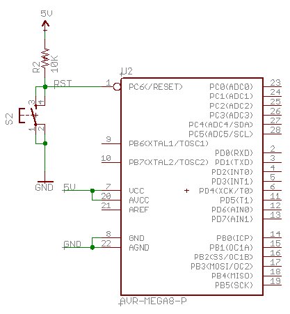
Beginning Embedded Electronics - 2
Acquire all the components required for this lecture here. It is highly recommended to obtain a multimeter with a continuity setting. A quality multimeter with this feature typically costs around $60, while premium models can reach $300. The $60 option...
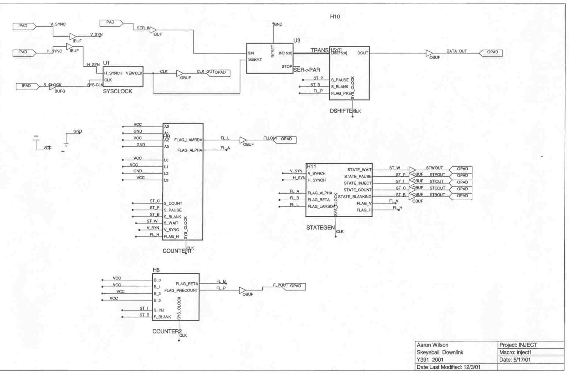
Downlink Project Description
The Skeyeball project is an ongoing initiative within the Indiana University System Design Methods Laboratory, aimed at providing graduate and undergraduate students with opportunities to engage in embedded system design and implement various projects. The downlink segment of the project...
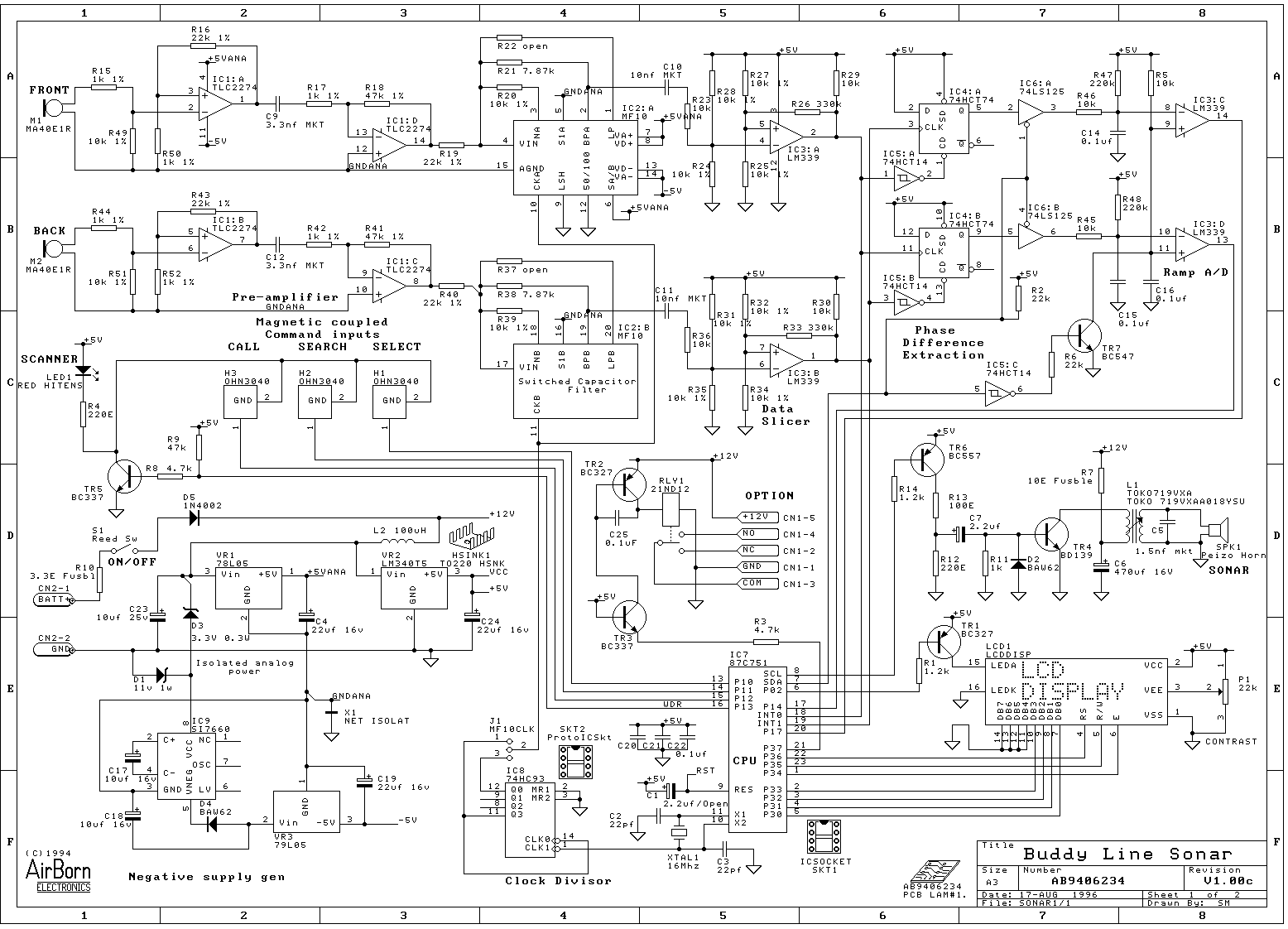
AirBorn Electronics project
Embedded system design engineers create examples of their work from the 1990s era.
Embedded systems have evolved significantly since the 1990s, and the design work from that period reflects the technological limitations and innovations of the time. Engineers in this field...