


Interfacing Relay To Microcontroller
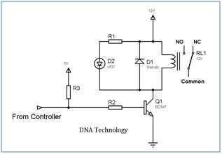
Description: Relays are devices which allow low power circuits to switch a relatively high Current/Voltage ON/OFF. For a relay to operate a suitable pull-in & holding current should be passed through its coil. Generally relay coils are designed to operate from a particular voltage often its 5V or 12V. The function of relay driver circuit is to provide the necessary current (typically 25 to 70ma) to energize the relay coil. More: Figure 1 shows the basic relay driver circuit. As you can see an NPN transistor BC547 is being used to control the relay. The transistor is driven into saturation (turned ON) when a LOGIC 1 is written on the PORT PIN thus turning ON the relay.
The relay driver circuit serves as an interface between low-power control signals and high-power loads. In this specific configuration, the circuit utilizes an NPN transistor, specifically the BC547, to switch the relay. The relay operates on a specified voltage, typically 5V or 12V, and requires a certain amount of current to activate its coil, which is generally between 25mA to 70mA.
The operation begins when a logic high signal (LOGIC 1) is applied to the base of the BC547 transistor. This signal allows current to flow from the collector to the emitter, effectively driving the transistor into saturation. In this state, the transistor acts as a closed switch, allowing a larger current to flow through the relay coil. This current energizes the relay, causing it to switch its contacts and control the connected load.
The relay itself consists of an electromagnetic coil and a set of contacts. When the coil is energized, it generates a magnetic field that attracts a movable armature, causing the contacts to either open or close, depending on the relay's design. This action can control various devices, such as motors, lights, or other high-voltage appliances, without exposing the low-power control circuit to high voltages or currents.
It is essential to ensure that the transistor is appropriately biased to operate within its safe limits, preventing damage during operation. Additionally, a flyback diode is often connected in parallel with the relay coil to protect the transistor from voltage spikes generated when the relay is de-energized. This diode allows the inductive kickback generated by the collapsing magnetic field of the relay coil to dissipate safely, thus prolonging the lifespan of the transistor and ensuring reliable operation of the circuit.Relays are devices which allow low power circuits to switch a relatively high Current/Voltage ON/OFF. For a relay to operate a suitable pull-in & holding current should be passed through its coil. Generally relay coils are designed to operate from a particular voltage often its 5V or 12V. The function of relay driver circuit is to provide the necessary current (typically 25 to 70ma) to energize the relay coil.
Figure 1 shows the basic relay driver circuit. As you can see an NPN transistor BC547 is being used to control the relay. The transistor is driven into saturation (turned ON) when a LOGIC 1 is written on the PORT PIN thus turning ON the relay. The relay
The relay driver circuit serves as an interface between low-power control signals and high-power loads. In this specific configuration, the circuit utilizes an NPN transistor, specifically the BC547, to switch the relay. The relay operates on a specified voltage, typically 5V or 12V, and requires a certain amount of current to activate its coil, which is generally between 25mA to 70mA.
The operation begins when a logic high signal (LOGIC 1) is applied to the base of the BC547 transistor. This signal allows current to flow from the collector to the emitter, effectively driving the transistor into saturation. In this state, the transistor acts as a closed switch, allowing a larger current to flow through the relay coil. This current energizes the relay, causing it to switch its contacts and control the connected load.
The relay itself consists of an electromagnetic coil and a set of contacts. When the coil is energized, it generates a magnetic field that attracts a movable armature, causing the contacts to either open or close, depending on the relay's design. This action can control various devices, such as motors, lights, or other high-voltage appliances, without exposing the low-power control circuit to high voltages or currents.
It is essential to ensure that the transistor is appropriately biased to operate within its safe limits, preventing damage during operation. Additionally, a flyback diode is often connected in parallel with the relay coil to protect the transistor from voltage spikes generated when the relay is de-energized. This diode allows the inductive kickback generated by the collapsing magnetic field of the relay coil to dissipate safely, thus prolonging the lifespan of the transistor and ensuring reliable operation of the circuit.Relays are devices which allow low power circuits to switch a relatively high Current/Voltage ON/OFF. For a relay to operate a suitable pull-in & holding current should be passed through its coil. Generally relay coils are designed to operate from a particular voltage often its 5V or 12V. The function of relay driver circuit is to provide the necessary current (typically 25 to 70ma) to energize the relay coil.
Figure 1 shows the basic relay driver circuit. As you can see an NPN transistor BC547 is being used to control the relay. The transistor is driven into saturation (turned ON) when a LOGIC 1 is written on the PORT PIN thus turning ON the relay. The relay
Input switching circuit
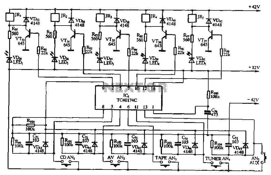
A relay is controlled by a closed circuit in a digital logic setup, utilizing a touch input switching circuit.
The described circuit involves a relay that operates based on a closed circuit condition within a digital logic framework. The relay serves...
Moto Alarm
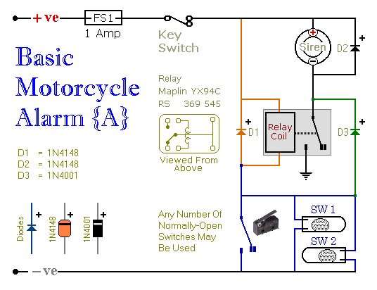
These are two easy to build relay-based alarms. You can use them to protect your motorcycle but they have many more applications. If you use relays with 6-volt coils, they'll protect your "Classic Bike". Both alarms are very small. The...
Relay Computer Two
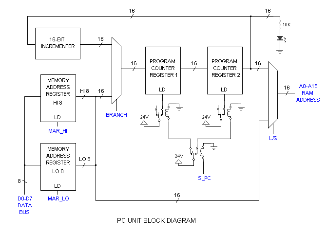
The simple relay adder was constructed using free NOS relays around 2005, with the intention of eventually creating a more complex version capable of running programs without occupying a large space like early computers. An impressive 415-relay computer was built...
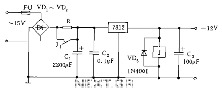
Relay type starting circuit diagram
The figure below illustrates the use of a relay in the starting circuit. The power input connects through a resistor R, which serves two purposes: first, it prevents a large current from the capacitor C1 from affecting the power supply...
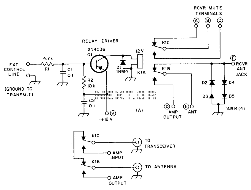
Tr circuit
R1 and R2 are carbon composition resistors labeled as Va or Vi. K1 is a 12 V DPDT DIP relay. Illustration A demonstrates the connection of the relay contacts for use with a separate transmitter-receiver combination. The circuit is designed...
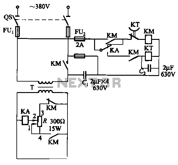
Three Relays AC arc welding machine circuit
The relays in the AC arc welding machine manage the load through a three-way power circuit, as depicted in Figure 522. The selected relay type is KA, operating at 24V. Additionally, the time relay KT is of the JS7 model,...
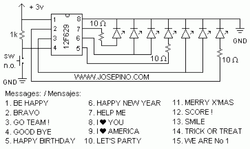
ON/OFF button using Microcontrollers
Using a switch to power up your microcontroller projects may not be a good idea if you need to "wake" the PIC during some events. For example: A metal detector sends a pulse indicating a car is ready to enter...
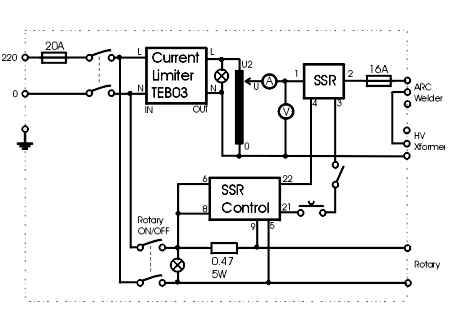
Power Control Unit
This shows the overall circuit diagram of the power control unit. On the left, there is a main relay controlled by the key switch.
The power control unit circuit diagram illustrates the primary components and their interconnections for managing electrical power...
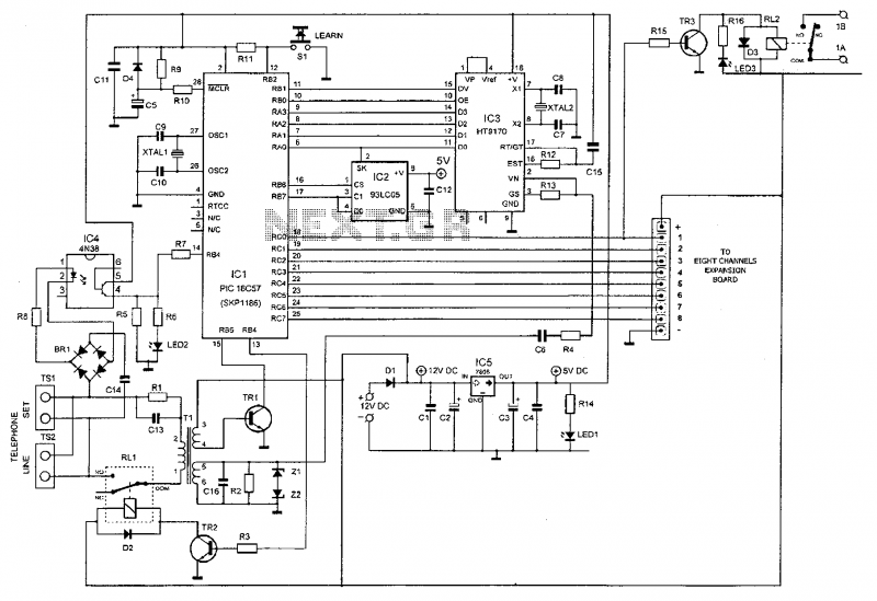
Microcontroller Based Telephone Remote Control Circuit
This device enables remote control of various appliances (up to eight with suitable add-on expansion boards) such as lights, water heaters, air conditioning, plant watering systems, alarms, etc., via a relay. It allows users to perform actions such as watering...