


Interfacing RTC with Microcontroller
#RTC
#microcontroller
#interfacing
#real-time clock
#data communication
#embedded systems
#timekeeping
#I2C
#SPI
#battery backup
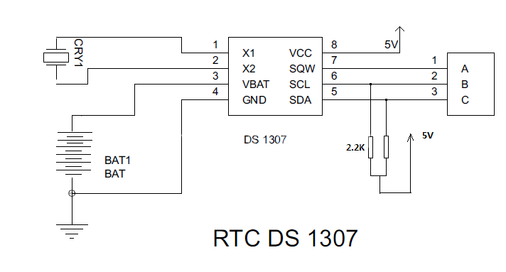
Description: Steps involved in interfacing a Real-Time Clock (RTC) with a microcontroller. The RTC remains powered even when the device is turned off. The microcontroller must interface with the RTC to retrieve the data.
To interface an RTC with a microcontroller, several steps must be followed to ensure proper communication and data retrieval. The RTC is typically powered by a backup battery, allowing it to maintain accurate timekeeping even when the main power is off.
1. **Component Selection**: Choose an appropriate RTC chip, such as the DS3231 or PCF8563, which supports I2C or SPI communication protocols. Ensure compatibility with the microcontroller being used.
2. **Power Supply**: Connect the RTC to a suitable power supply. The VCC pin of the RTC should be connected to the power source, while the ground (GND) pin should be connected to the common ground of the microcontroller.
3. **Communication Interface**: Depending on the chosen RTC, connect the communication pins. For I2C, connect the SDA (data line) and SCL (clock line) pins of the RTC to the corresponding pins on the microcontroller. For SPI, connect the MOSI, MISO, SCK, and CS pins accordingly.
4. **Pull-up Resistors**: If using I2C, it is crucial to include pull-up resistors (typically 4.7kΩ) on the SDA and SCL lines to ensure proper signal levels.
5. **Microcontroller Configuration**: Configure the microcontroller’s I2C or SPI interface in the firmware. This includes setting the correct clock frequency and initializing the communication protocol.
6. **Data Retrieval**: Implement the necessary code to read the time and date data from the RTC. This typically involves sending a command to the RTC to request the current time and then reading the response back into the microcontroller.
7. **Continuous Operation**: If required, set up an interrupt or a polling mechanism to periodically check the RTC for updates or to synchronize the microcontroller's time with the RTC.
8. **Testing**: Finally, test the entire setup to ensure that the RTC is functioning correctly and that the microcontroller can successfully read the time data. This may involve debugging communication issues or verifying the accuracy of the timekeeping.
By following these steps, a reliable interface between the RTC and the microcontroller can be established, allowing for accurate timekeeping in various applications.steps involved in interfacing RTC with Microcontroller. There is a RTC that is kept ON even even is the device is turned OFF. Microcontroller has to interface the RTC to get the data..
To interface an RTC with a microcontroller, several steps must be followed to ensure proper communication and data retrieval. The RTC is typically powered by a backup battery, allowing it to maintain accurate timekeeping even when the main power is off.
1. **Component Selection**: Choose an appropriate RTC chip, such as the DS3231 or PCF8563, which supports I2C or SPI communication protocols. Ensure compatibility with the microcontroller being used.
2. **Power Supply**: Connect the RTC to a suitable power supply. The VCC pin of the RTC should be connected to the power source, while the ground (GND) pin should be connected to the common ground of the microcontroller.
3. **Communication Interface**: Depending on the chosen RTC, connect the communication pins. For I2C, connect the SDA (data line) and SCL (clock line) pins of the RTC to the corresponding pins on the microcontroller. For SPI, connect the MOSI, MISO, SCK, and CS pins accordingly.
4. **Pull-up Resistors**: If using I2C, it is crucial to include pull-up resistors (typically 4.7kΩ) on the SDA and SCL lines to ensure proper signal levels.
5. **Microcontroller Configuration**: Configure the microcontroller’s I2C or SPI interface in the firmware. This includes setting the correct clock frequency and initializing the communication protocol.
6. **Data Retrieval**: Implement the necessary code to read the time and date data from the RTC. This typically involves sending a command to the RTC to request the current time and then reading the response back into the microcontroller.
7. **Continuous Operation**: If required, set up an interrupt or a polling mechanism to periodically check the RTC for updates or to synchronize the microcontroller's time with the RTC.
8. **Testing**: Finally, test the entire setup to ensure that the RTC is functioning correctly and that the microcontroller can successfully read the time data. This may involve debugging communication issues or verifying the accuracy of the timekeeping.
By following these steps, a reliable interface between the RTC and the microcontroller can be established, allowing for accurate timekeeping in various applications.steps involved in interfacing RTC with Microcontroller. There is a RTC that is kept ON even even is the device is turned OFF. Microcontroller has to interface the RTC to get the data..
Night Light Saver
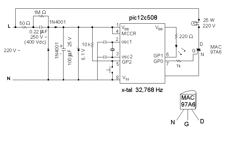
A Microchip PIC12C508 8-pin CMOS microcontroller controls a night light, turning it on and off at preset times every day. It is designed to save energy, produce no electromagnetic interference (EMI), and operate without batteries, featuring a built-in lamp fixture...
i2c interface to USB interface
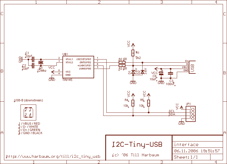
The i2c-tiny-usb project is an open source/open hardware project. The goal of i2c-tiny-usb is to provide a cheap generic i2c interface to be attached to the usb. It is meant as a replacement for those simple and cheap printer port...
Controlling high-current circuits
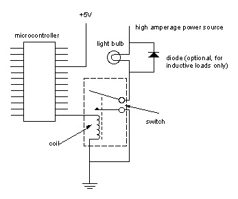
Digital output from a microcontroller is typically a low-amperage signal. For example, when a pin is set HIGH on the microcontroller (in Wiring/Arduino, it is digitalWrite(somePin, HIGH);), the voltage from that pin is usually +3.3V or +5V, with the current...
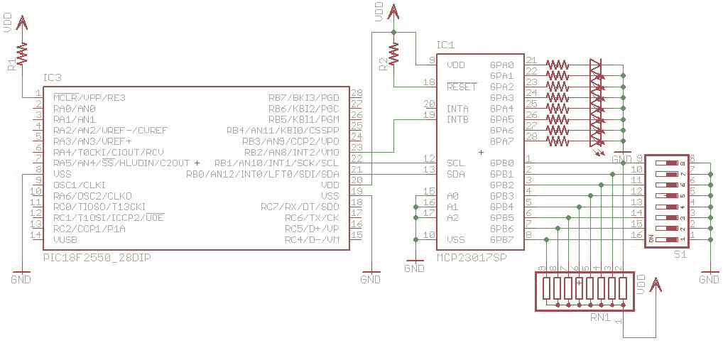
I2C using (MSSP)
I2C are widely use for to communicate with external peripheral such as port expender, EEPROM, Real Time Clock etc. The Master Synchronous Serial Port (MSSP) module in PIC18 can be used to communicated with I2C peripheral. MSSP module can be...
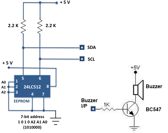
Experimental I/O board for microcontrollers
For beginners experiencing similar challenges, a general-purpose I/O board is recommended to minimize prototyping time and maximize space on the breadboard for projects. The construction of this board is straightforward. Basic I/O devices can be soldered onto a general-purpose perforated...
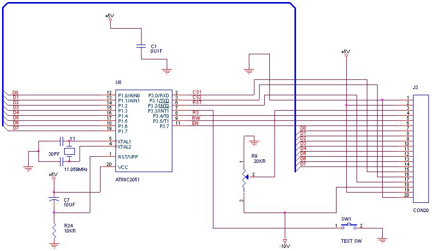
graphical LCDs with a microcontroller
How can graphical LCDs be controlled using a microcontroller? Is there any datasheet available?
Graphical LCDs (Liquid Crystal Displays) are widely used in various electronic applications for displaying complex graphics and text. To control these displays with a microcontroller, several steps...
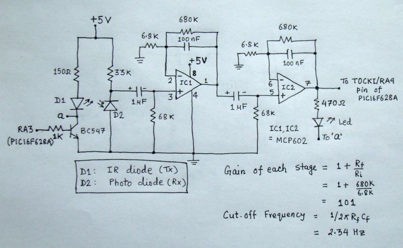
Microcontroller measures heart rate through fingertip
The reflected infrared (IR) signal detected by the photodiode is sent to a signal conditioning circuit, which filters out unwanted signals and amplifies the desired output.
The circuit begins with a photodiode that captures the reflected IR signals. The photodiode operates...
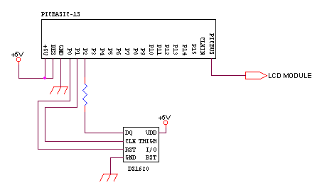
spi circuit
SPI Integrated Circuit Bus, IC Buses, an IC, Chip-to-Chip Bus Serial Peripheral Interface, Integrated Circuit Bus types, and IC Bus Electrical Interface Descriptions. Peripheral Interface (SPI) circuit is a.
The Serial Peripheral Interface (SPI) is a synchronous serial communication protocol...
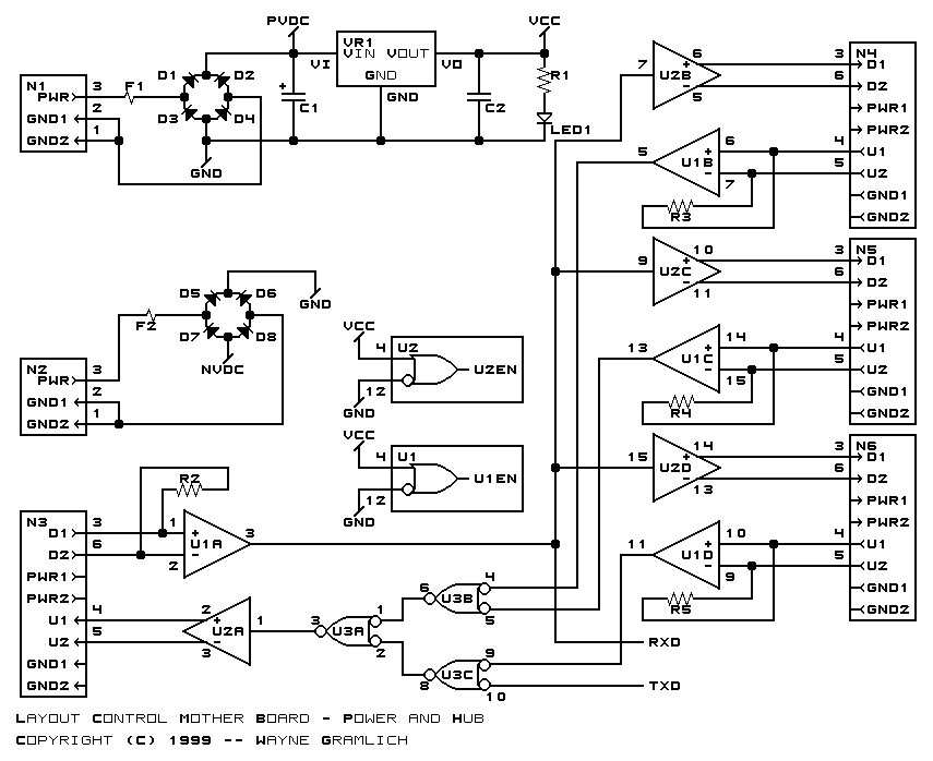
Layout Control Mother Board
The layout control motherboard is designed to facilitate the management of various sections of a layout. It features a microcontroller that connects to the MRNet bus and multiple slots for inexpensive control and sensor boards. All control and sensor boards...