


light weight data capture and signal generator
#PIC18f4620
#data acquisition
#signal generator
#PCB
#DAQ
#microcontroller programming
#sensor interface
#data capture
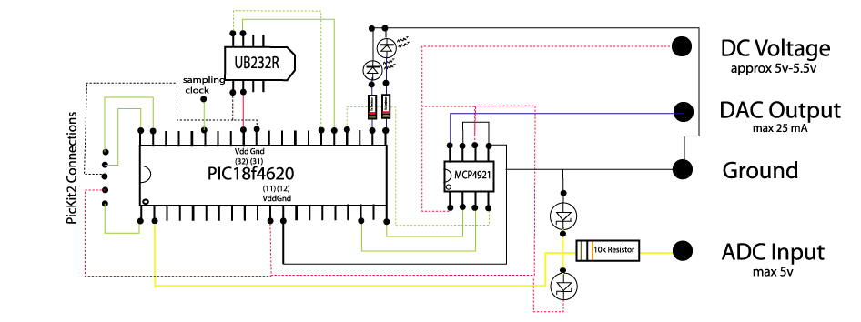
Description: The circuit below demonstrates how to construct a DAQ_LITE device, accompanied by an image of the finished PCB board. It is important to note that the 80mA fuse depicted in the image and the nearby protection diode are recommended components but not essential. After assembling the circuit, programming the PIC18F4620 microcontroller is necessary to enable data reading and writing to and from a computer. MPLAB project files are available for this purpose. A PICkit programmer is required to program the PIC18F4620, and the schematic illustrates the necessary connections for the PICkit 2.
The DAQ_LITE circuit is designed for data acquisition purposes, leveraging the capabilities of the PIC18F4620 microcontroller. This microcontroller is equipped with multiple analog-to-digital converters (ADCs) that facilitate the conversion of analog signals into digital data, which can then be processed or transmitted to a computer for analysis.
The PCB layout should be carefully designed to accommodate the microcontroller, necessary passive components, and the recommended fuse and diode. The fuse serves as a protective measure against overcurrent conditions, while the diode provides reverse polarity protection, ensuring the circuit operates safely under varying input conditions.
The programming of the PIC18F4620 microcontroller is a critical step. The MPLAB project files, which are provided, include the necessary firmware to configure the microcontroller's ADC settings, communication protocols, and data handling routines. The PICkit programmer facilitates the uploading of this firmware to the microcontroller, enabling it to perform its intended functions effectively.
Connections for the PICkit 2 programmer are essential for programming the microcontroller. These connections typically include the MCLR (Master Clear), VDD (supply voltage), VSS (ground), and data lines for programming. Proper attention to these connections is crucial for successful programming and operation of the DAQ_LITE circuit.
Overall, the DAQ_LITE circuit is a versatile and efficient solution for data acquisition applications, providing a foundation for further development and integration into larger systems.The circuit below illustrates how to build your own daq_lite - also shown is a photo of a completed PCB board. Note that the 80mA fuse shown in the photo and the protection diode close to it are recommended but not necessary.
Once you`ve built the circuit you`ll need to program the PIC18f4620 microcontroller to set it up to read and write to/from a computer - MPLAB project files are availble here for this purpose. Note that you`ll need a PicKit programmer to porgamme the PIC18f4620 - the PicKit2 connections shown in the schematic are required solely for this purpose.
The DAQ_LITE circuit is designed for data acquisition purposes, leveraging the capabilities of the PIC18F4620 microcontroller. This microcontroller is equipped with multiple analog-to-digital converters (ADCs) that facilitate the conversion of analog signals into digital data, which can then be processed or transmitted to a computer for analysis.
The PCB layout should be carefully designed to accommodate the microcontroller, necessary passive components, and the recommended fuse and diode. The fuse serves as a protective measure against overcurrent conditions, while the diode provides reverse polarity protection, ensuring the circuit operates safely under varying input conditions.
The programming of the PIC18F4620 microcontroller is a critical step. The MPLAB project files, which are provided, include the necessary firmware to configure the microcontroller's ADC settings, communication protocols, and data handling routines. The PICkit programmer facilitates the uploading of this firmware to the microcontroller, enabling it to perform its intended functions effectively.
Connections for the PICkit 2 programmer are essential for programming the microcontroller. These connections typically include the MCLR (Master Clear), VDD (supply voltage), VSS (ground), and data lines for programming. Proper attention to these connections is crucial for successful programming and operation of the DAQ_LITE circuit.
Overall, the DAQ_LITE circuit is a versatile and efficient solution for data acquisition applications, providing a foundation for further development and integration into larger systems.The circuit below illustrates how to build your own daq_lite - also shown is a photo of a completed PCB board. Note that the 80mA fuse shown in the photo and the protection diode close to it are recommended but not necessary.
Once you`ve built the circuit you`ll need to program the PIC18f4620 microcontroller to set it up to read and write to/from a computer - MPLAB project files are availble here for this purpose. Note that you`ll need a PicKit programmer to porgamme the PIC18f4620 - the PicKit2 connections shown in the schematic are required solely for this purpose.
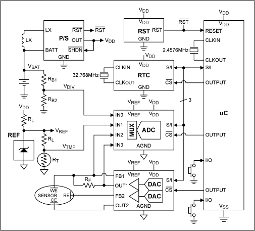
The MAX1407 Complete Data Acquisition System Simplifies Your System Designs
A design example for a portable data acquisition system is provided, which significantly simplifies the circuit design task.
The portable data acquisition system is designed to capture, process, and store data from various sensors and input devices. This system typically includes...
Express PCB
Our Free PCB software is a snap to learn and use. For the first time, designing circuit boards is simple for the beginner and efficient for the professional. Our board manufacturing service makes top quality two and four layer PCBs....
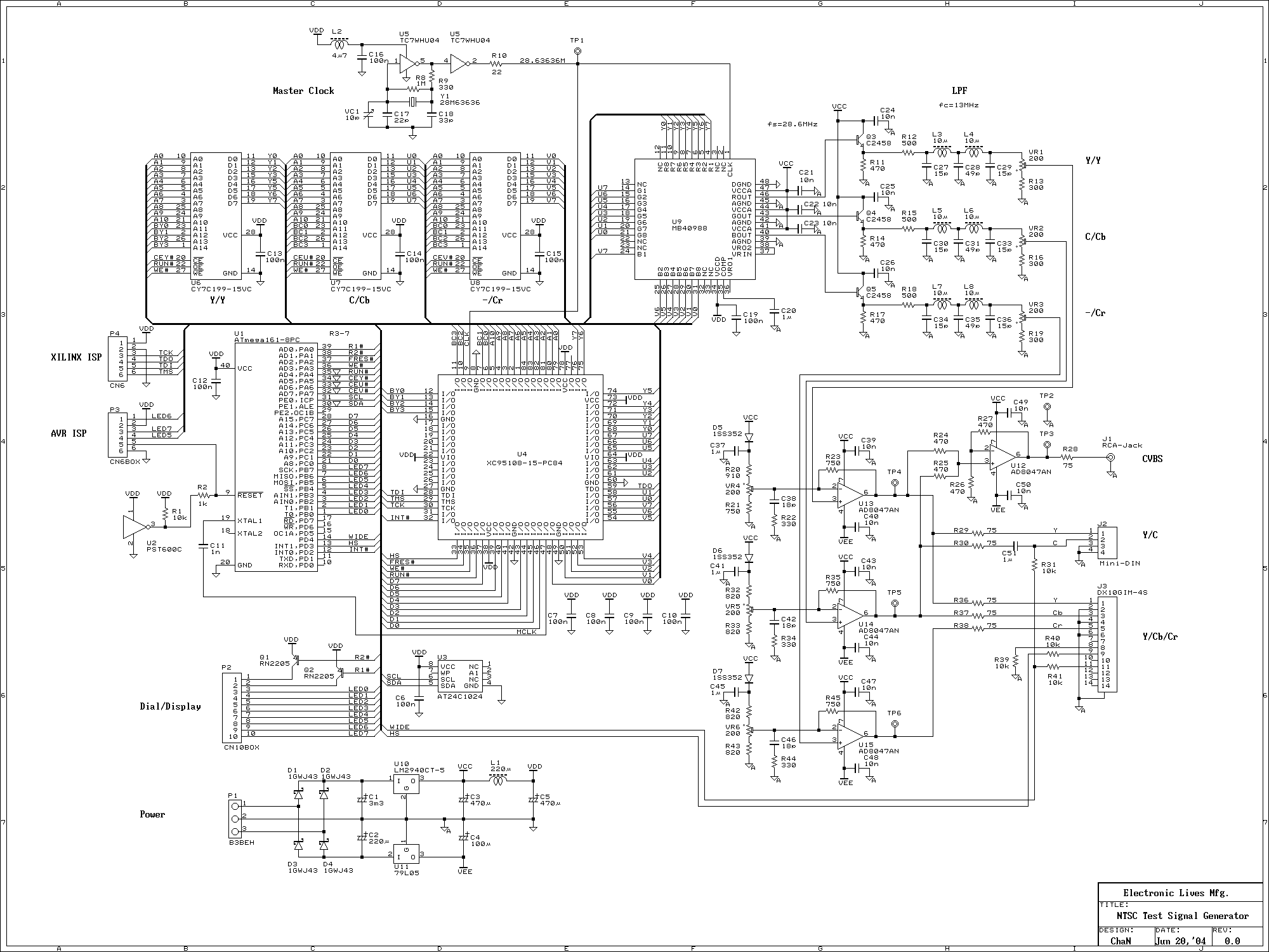
Test Signal Generator
This signal generator uses a three channel DAC to generate Composite video signal (CVBS) and S video signal (Y/C separated) at the same time, left one channel is not used in NTSC format. It is assigned for one of the...
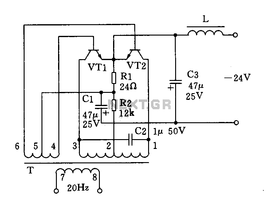
20Hz signal generator (phone-ringing) circuit diagram
The circuit described is a 20Hz signal generator suitable for telephone ringing systems, alarm systems, and various other electronic applications. It consists of a transformer (T) and two transistors (VT1 and VT2), forming a push-pull oscillator. The two transistors operate...
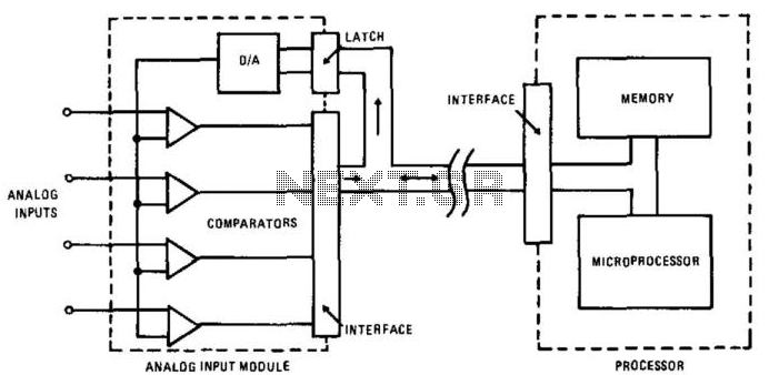
Data Acquisition System Ii
In this circuit, an HA-4900 series comparator is utilized alongside a digital-to-analog (D/A) converter to create a versatile, multichannel analog input for a data acquisition system. The processor first transmits an address to the D/A converter, after which it reads...
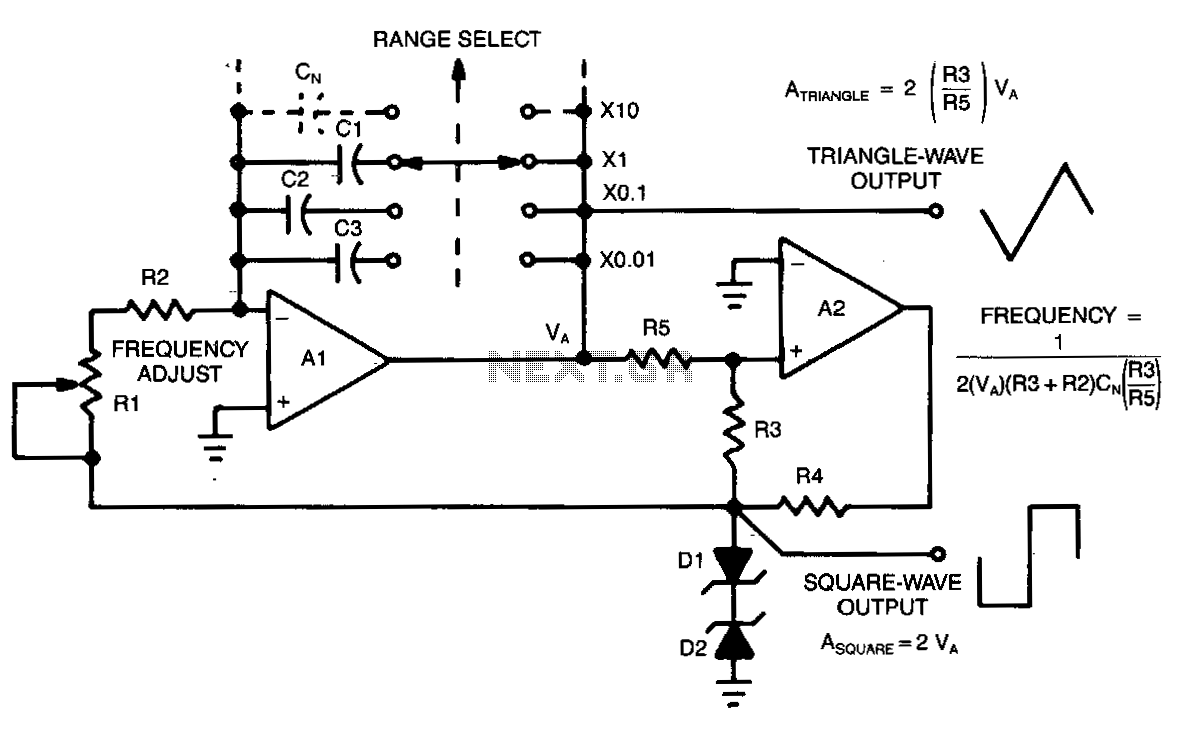
Two-function-signal-generator
This circuit allows for continuous variation of the frequencies of the triangle and square waves produced, covering a full decade. When the resistance of RS is approximately equal to R3, the amplitudes of the two waveforms will be equal (A_SQUARE...
wifilapper on a porsche 944 turbo t136
Following the successful development of a data acquisition box for a Porsche Chumpcar, which enabled the collection of lap times and telemetry data during an Auto Club Speedway race weekend, a new IOIO box is being designed specifically for a...
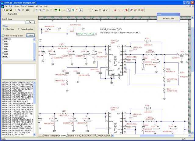
Free-PCB
FreePCB is a free, open-source printed circuit board layout editor for Microsoft Windows, released under the GNU General Public License. It was designed to be easy to learn and easy to use, yet capable of professional-quality work. More: It does...
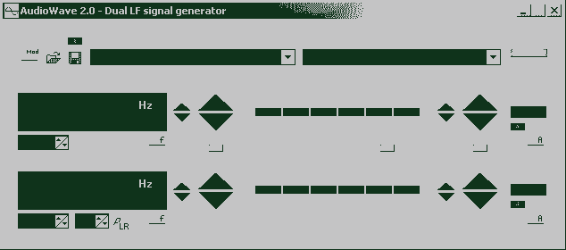
AudioWave 2.0
With AudioWave 2.0 your soundcard becomes a comfortable LF-signal-generator, which produces signals from 1Hz to 20 kHz with a resolution of 1 Hz. Phase shift between left and right channel is adjustable from 180° to +180° and an attenuator can...