


mc board
#AT89C1051
#AT89C2051
#AT89C4051
#voltage regulation
#oscillator
#reset circuit
#DIP switch
#solder connections
#development board
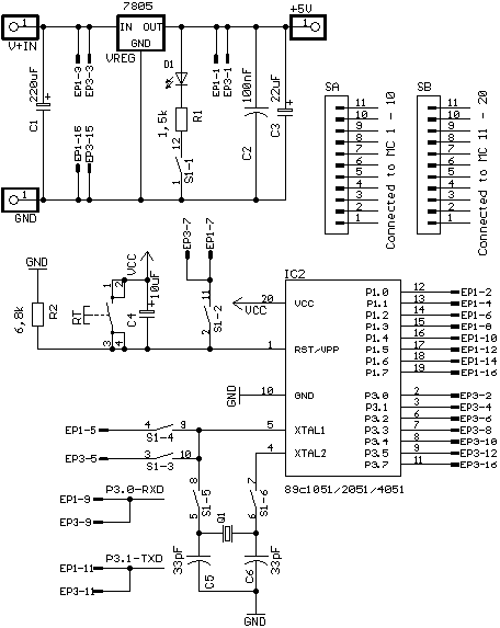
Description: The Flash MC Experimenting Board I serves as an excellent platform for development activities involving Atmel Flash microcontrollers, specifically the AT89C1051, AT89C2051, and AT89C4051. This board is suitable for both beginners and experienced developers, as it provides a universal and standardized platform that facilitates the realization of various projects. Essential components for a Flash microcontroller application are integrated directly onto the Flash MC Experimenting Board I. These components include voltage regulation and stabilization, an oscillator, Power-On Reset (POR) wiring, a reset switch, a 6x DIP switch for configuration purposes, pin rows for solder connections, and additional features.
The Flash MC Experimenting Board I is designed to enhance the development process for Atmel microcontrollers by providing a comprehensive set of features that streamline the prototyping and testing phases. The integrated voltage regulation and stabilization circuitry ensures that the microcontroller operates reliably under varying power conditions, which is critical for maintaining performance and preventing damage. The oscillator circuit is essential for providing the necessary clock signal to the microcontroller, allowing for precise timing and synchronization of operations.
The inclusion of Power-On Reset (POR) wiring is a significant feature, as it guarantees that the microcontroller starts in a known state after power is applied, preventing erratic behavior during startup. The reset switch allows users to manually reset the microcontroller, facilitating troubleshooting and testing of various functions.
The 6x DIP switch included on the board provides a flexible means of configuring various operational parameters without the need for complex wiring or additional components. This feature is particularly useful for developers who wish to test different configurations rapidly.
Furthermore, the presence of pin rows for solder connections enhances the board's versatility, enabling users to add custom components or interfaces as required for their specific applications. Overall, the Flash MC Experimenting Board I is a robust and versatile tool for anyone working with Atmel Flash microcontrollers, supporting a wide range of development projects from simple experiments to complex applications.The Flash MC Experimenting Board I is an ideal platform for all developements in conjunction with the Atmel Flash microcontrollers AT89C1051, AT89C2051 and AT89C4051. It is not only recommendable for starters but also very much recommendable for the advanced developer due to the fact that it offers an universal and standardized platform which enables to bring almost anything thinkable into reality.
All basic parts of a Flash microcontroller applikation are located directly on the Flash MC Experimenting Board I. To these belong the voltage regulation and stabilisation, the oscillator, the POR-wiring (Power On -> Reset), a reset switch, a 6x DIP switch for all kinds of configuration issues, pin rows for solder connections and lots more..
The Flash MC Experimenting Board I is designed to enhance the development process for Atmel microcontrollers by providing a comprehensive set of features that streamline the prototyping and testing phases. The integrated voltage regulation and stabilization circuitry ensures that the microcontroller operates reliably under varying power conditions, which is critical for maintaining performance and preventing damage. The oscillator circuit is essential for providing the necessary clock signal to the microcontroller, allowing for precise timing and synchronization of operations.
The inclusion of Power-On Reset (POR) wiring is a significant feature, as it guarantees that the microcontroller starts in a known state after power is applied, preventing erratic behavior during startup. The reset switch allows users to manually reset the microcontroller, facilitating troubleshooting and testing of various functions.
The 6x DIP switch included on the board provides a flexible means of configuring various operational parameters without the need for complex wiring or additional components. This feature is particularly useful for developers who wish to test different configurations rapidly.
Furthermore, the presence of pin rows for solder connections enhances the board's versatility, enabling users to add custom components or interfaces as required for their specific applications. Overall, the Flash MC Experimenting Board I is a robust and versatile tool for anyone working with Atmel Flash microcontrollers, supporting a wide range of development projects from simple experiments to complex applications.The Flash MC Experimenting Board I is an ideal platform for all developements in conjunction with the Atmel Flash microcontrollers AT89C1051, AT89C2051 and AT89C4051. It is not only recommendable for starters but also very much recommendable for the advanced developer due to the fact that it offers an universal and standardized platform which enables to bring almost anything thinkable into reality.
All basic parts of a Flash microcontroller applikation are located directly on the Flash MC Experimenting Board I. To these belong the voltage regulation and stabilisation, the oscillator, the POR-wiring (Power On -> Reset), a reset switch, a 6x DIP switch for all kinds of configuration issues, pin rows for solder connections and lots more..
Little dipper
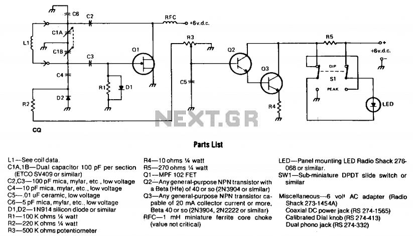
The circuit consists of two fundamental components: the oscillator and the detector. The oscillator employs a Field Effect Transistor (FET) in a Colpitts configuration. The energy circulating within the oscillator's tank is coupled through capacitor C4 to the detector circuit,...
The oscillator and trigger circuit with operational amplifier
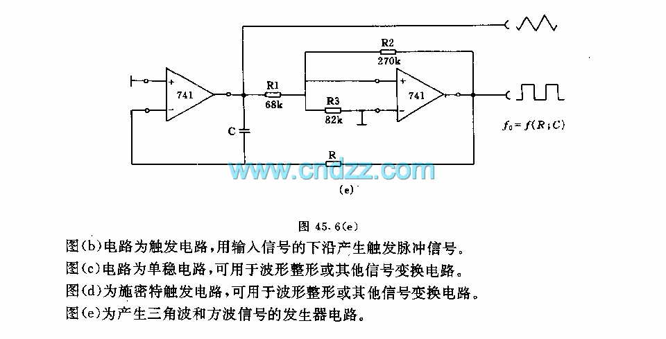
Figure a illustrates a multivibrator circuit capable of generating a square wave signal. Figure b depicts a flip-flop circuit that utilizes the falling edge of the input signal to produce a trigger pulse signal. Figure c represents a monostable circuit,...
0-30 VDC Stabilized Power Supply with Current Control 0.002-3 A
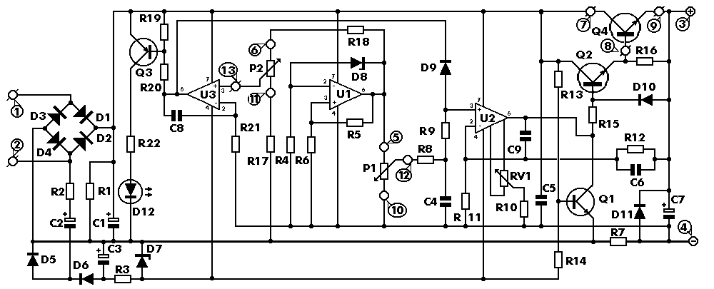
The circuit begins with a step-down mains transformer featuring a secondary winding rated at 24 V/3 A, which connects across the input points at pins 1 and 2. The quality of the output supply is directly related to the transformer's...
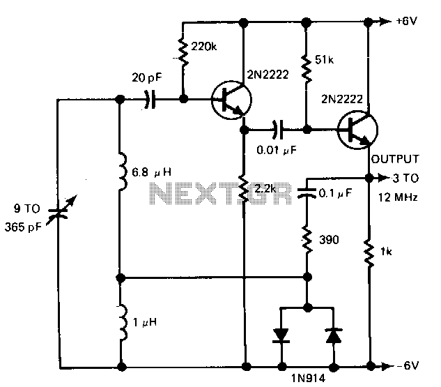
Wide-range-oscillator
The gain control enables the oscillator to maintain a nearly constant output across its range. The circuit operates within a frequency range of 160 kHz to 12 MHz while producing a consistent amplitude.
The oscillator circuit described utilizes a gain control...
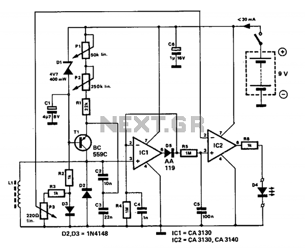
Metallic pipe detector
This circuit employs a 15-kHz oscillator coil. When metal is removed from the energy field, the oscillator voltage is rectified and compared to a reference. A decrease in oscillator voltage activates comparator IC2, causing D4 (LED) to turn off.
L1 consists...
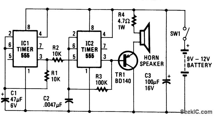
HEE HAW ELECTRONIC SIREN
The oscillator based on IC2 generates sound, with its output linked to the base of TR1, which amplifies the signal to drive the speaker. Resistor R4 is included to limit the current through TR1 to a safe level. The oscillation...
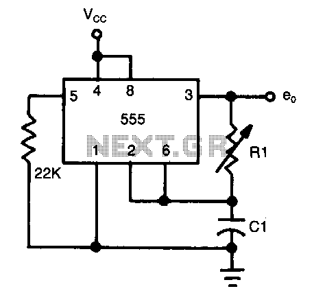
Half-duty-cycle-oscillator
The frequency of oscillation depends on the Rl/Cl time constant, allowing for frequency adjustment by varying Rl. This is a basic circuit.
The described circuit operates based on the relationship between resistance (Rl) and capacitance (Cl), which together form a time...
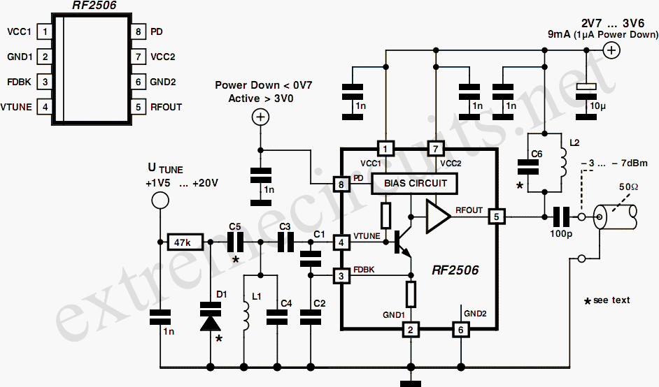
10 to 1000 MHz Oscillator circuit with RF2506
Today, it is no longer necessary to use discrete components for constructing oscillators. Many manufacturers now offer ready-made voltage-controlled oscillator (VCO) integrated circuits (ICs) that require only a few external components to determine the frequency. An example of such an...
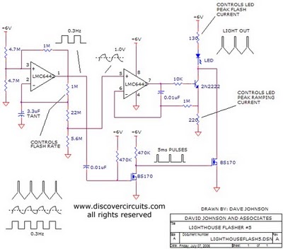
Schematic Diagram Schema HO Train Model Lighthouse Flasher
The aboriginal accessory forms a typical oscillator circuit that produces both a triangle waveform signal and a square wave signal. The triangle signal is fed into a voltage regulator circuit, which converts the triangle voltage signal to a triangle current...