


Microcontroller Verification Password system
#password system
#8-bit
#logic circuit
#authentication
#security
#input/output
#microprogram
#comparison
#user verification
#output port
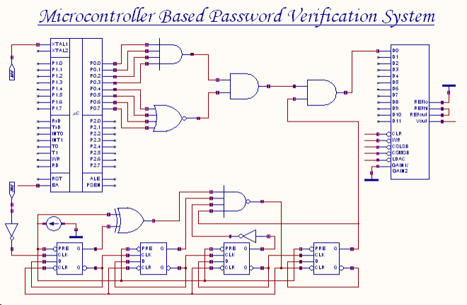
Description: An 8-bit password serves as the input to this system. The password entered by the user is compared with the actual password, which is set in the microcontroller through a microprogram. The outcome of this comparison process generates an 8-bit output at the output port, which is then directed to a logic circuit. If the user-entered password is correct, the output of the logic circuit will be high.
The described system utilizes an 8-bit password verification mechanism, which is fundamental in various security applications. The microcontroller plays a crucial role in this process, as it stores the actual password and executes the comparison logic. Upon receiving the user input, the microcontroller reads the 8-bit password and compares it against the stored password value using a binary comparison algorithm.
The comparison process involves checking each of the 8 bits of the entered password against the corresponding bits of the stored password. If all bits match, the microcontroller generates an 8-bit output signal indicating a successful verification. This output is connected to a logic circuit designed to interpret the result of the comparison.
The logic circuit may consist of basic logic gates such as AND, OR, and NOT gates, configured to produce a high output signal when the comparison result is positive. Specifically, if the output from the microcontroller indicates that the user-entered password matches the stored password, the logic circuit outputs a high signal, which can then be used to trigger subsequent actions, such as unlocking a device or granting access to a secure system.
In summary, this circuit design not only emphasizes the importance of secure password handling but also illustrates the integration of microcontroller functionalities with basic logic circuitry to achieve reliable password verification.An 8-bit password is the input to this system. The password entered by the user is compared with the actual password (password set in the microcontroller using the microprogram) by the microcontroller. The result of the comparison process is an 8-bit output at the output port, which is fed to a logic circuit.
If the user-password is correct, the o utput of the logic circuit will be high.
The described system utilizes an 8-bit password verification mechanism, which is fundamental in various security applications. The microcontroller plays a crucial role in this process, as it stores the actual password and executes the comparison logic. Upon receiving the user input, the microcontroller reads the 8-bit password and compares it against the stored password value using a binary comparison algorithm.
The comparison process involves checking each of the 8 bits of the entered password against the corresponding bits of the stored password. If all bits match, the microcontroller generates an 8-bit output signal indicating a successful verification. This output is connected to a logic circuit designed to interpret the result of the comparison.
The logic circuit may consist of basic logic gates such as AND, OR, and NOT gates, configured to produce a high output signal when the comparison result is positive. Specifically, if the output from the microcontroller indicates that the user-entered password matches the stored password, the logic circuit outputs a high signal, which can then be used to trigger subsequent actions, such as unlocking a device or granting access to a secure system.
In summary, this circuit design not only emphasizes the importance of secure password handling but also illustrates the integration of microcontroller functionalities with basic logic circuitry to achieve reliable password verification.An 8-bit password is the input to this system. The password entered by the user is compared with the actual password (password set in the microcontroller using the microprogram) by the microcontroller. The result of the comparison process is an 8-bit output at the output port, which is fed to a logic circuit.
If the user-password is correct, the o utput of the logic circuit will be high.
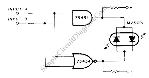
Coincidence Detector for Logic Signals
This is a coincidence detector circuit. This circuit is very useful for monitoring complex logic circuits. This circuit has two inputs, A and B. If A and B are...
The coincidence detector circuit is designed to identify when two input signals,...

OSU8 Microprocessor Project (1994)
OSU8 began as a student project in 1994 to create a simple but functional 8-bit microprocessor, starting with a definition of the architecture to implementation in a Xilinx FPGA chip, and full-custom CMOS implementation. Over a period of about six...
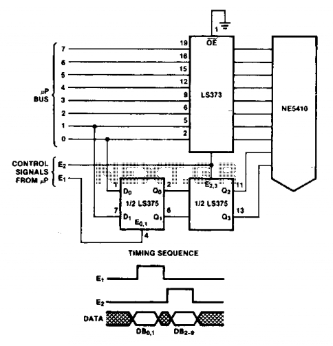
8-bit bus interface
The double latch technique ensures that valid data is latched to the Digital-to-Analog Converter (DAC) until it is updated by the E2 pulse. The timing of this process will depend on the specific processor utilized.
The double latch technique is a...
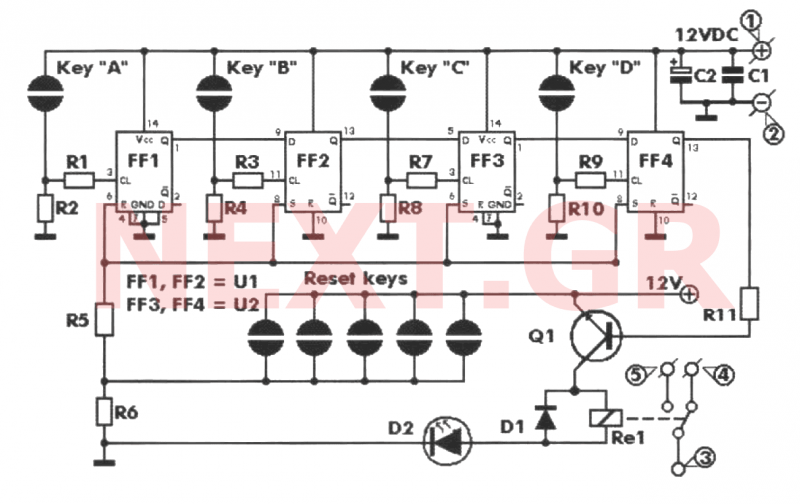
Key Code Combination High Security Door Lock
This project involves an electronic lock that supports numerous combinations, which can be easily modified. It unlocks only with the correct sequence of four consecutive numbers. A significant feature of this electronic lock is that the four numbers must be...

Security alarm
This alarm features both open-loop and closed-loop detection systems along with an automatic alarm shutoff mechanism. It provides a 15-second delay for exit and entrance. Additionally, the alarm activation time can be adjusted from 1 to 15 minutes.
The alarm system...

Midnight Security Light Circuit Schematic
Most thefts occur after midnight when individuals enter the second phase of sleep known as 'paradoxical sleep.' Here is an energy-saving circuit that causes...
An energy-saving circuit designed for security applications can be particularly beneficial during the late-night hours when individuals...
Security Monitor
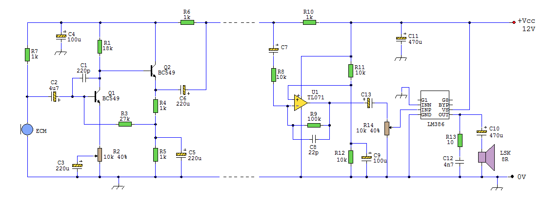
This circuit can be utilized in a garden setting to detect unusual sounds or wildlife noises. It can also monitor sounds around a car parked in a remote location. The cable used for the setup can either be visible or...
Locker Guard Locker Security Alarm Circuit Anti Theft
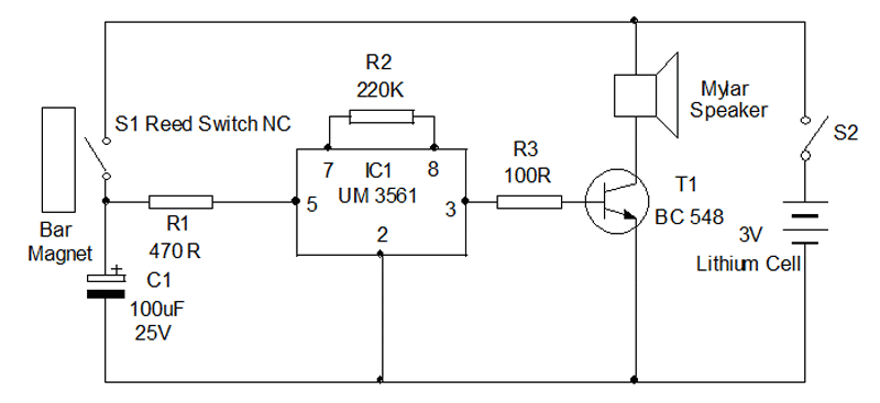
Locker Guard Circuit Diagram. This compact circuit is designed to protect a locker or almirah from burglary. If the locker is opened while in the armed state, the circuit triggers a loud police siren to deter the burglary attempt.
The Locker...
Home Security System
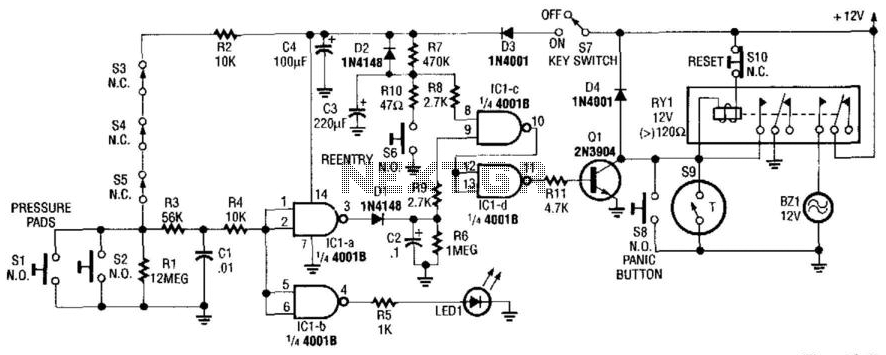
This alarm circuit activates when switches S1 through S5 are engaged. This action illuminates LED1 and triggers transistor Q1 through integrated circuits IC1C and IC1D. Relay RY1 is configured for self-latching. Switch S10 is utilized for resetting the circuit. When...