


Serial Voltmeter using the PIC16C71
#PIC16C71
#voltmeter
#serial communication
#voltage measurement
#PicBasic
#Visual Basic
#MSComm
#DC voltage
#measurement
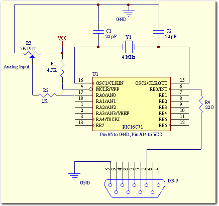
Building a serial voltage meter to measure from 0 to 5 volts DC is straightforward. Utilizing MeLabs PicBasic and Microsoft Visual Basic Version 5 Pro is essential, as the MSComm control required for communication is not available in the Visual Basic 5 Learning Edition. The PIC16C71 microcontroller simplifies the process further by incorporating a built-in A/D converter. The analog inputs AIN0, AIN1, AIN2, and AIN3 are assigned to pins 17, 18, 1, and 2, respectively.
To construct a serial voltage meter, the following components and steps are necessary:
1. **Microcontroller Selection**: The PIC16C71 is selected for its integrated A/D converter, which allows for direct measurement of analog voltage levels. This microcontroller can effectively convert the input voltage into a digital signal that can be transmitted serially to a PC.
2. **Analog Input Configuration**: The microcontroller’s pins 17, 18, 1, and 2 will be configured as analog inputs (AIN0 to AIN3). These pins will receive the voltage signals that need to be measured. Proper configuration in the firmware is essential to ensure accurate readings from the A/D converter.
3. **Programming Environment**: MeLabs PicBasic will be used to write the firmware for the PIC16C71. This programming environment is user-friendly and allows for straightforward manipulation of the microcontroller's features, including the A/D converter.
4. **Serial Communication Setup**: Microsoft Visual Basic Version 5 Pro is required to develop the PC interface. The MSComm control in Visual Basic is crucial for establishing serial communication between the microcontroller and the PC. This control allows for the transmission of the measured voltage values from the microcontroller to the PC for display and analysis.
5. **Power Supply Requirements**: Ensure that the microcontroller is powered adequately, typically with a regulated supply of 5 volts. The voltage meter should also include filtering capacitors to stabilize the power supply and reduce noise in the measurements.
6. **Circuit Design**: The schematic will include the PIC16C71 connected to the analog inputs, with resistors as necessary for voltage division if higher voltages are to be measured. Additionally, a serial connection (RS-232 or USB) will be established to connect the microcontroller to the PC.
7. **Calibration**: After assembling the circuit, calibration is necessary to ensure that the voltage readings are accurate. This may involve comparing the measured values against a known standard and adjusting the software accordingly.
By following these steps and utilizing the specified components, a functional serial voltage meter capable of measuring DC voltages from 0 to 5 volts can be successfully built. The integration of hardware and software components will facilitate real-time data monitoring and analysis, making this project an excellent introduction to microcontroller applications in electronics.Building a serial voltage meter to measure from 0 to 5 volts DC is actually pretty easy. Using MeLabs PicBasic, and Microsoft`s Visual Basic Version 5 Pro. You need Visual Basic Pro version because you will have to use Basic`s MSComm control. This control is not available in the Visual Basic 5 Learning Edition. The PIC16C71 simplifies the task even more by having a built in A/D converter. Pins 17, 18, 1, 2 are the analog inputs AIN0, AIN1, AIN2, AIN3 respectively. Disclaimer All files are found using legitimate search engine techniques. This site does not and will not condone hacking into sites to create the links it list. We will and do assume that all links found on the search engines we use are obtained in a legal manner and the webmasters are aware of the links listed on the search engines. If you find a URL that belongs to you, and you did not realize that it was "open to the public", please use the report button to notify the blogmaster of your request to remove it or it will remove within 24 hours.
This is not an invitation for webblog haters to spam with requests to remove content they feel that is objectionable and or unacceptable. Proof of URL ownership is required. NOTICE: This Blog Has Already Been Reviewed And Accepted By Blogger. com
To construct a serial voltage meter, the following components and steps are necessary:
1. **Microcontroller Selection**: The PIC16C71 is selected for its integrated A/D converter, which allows for direct measurement of analog voltage levels. This microcontroller can effectively convert the input voltage into a digital signal that can be transmitted serially to a PC.
2. **Analog Input Configuration**: The microcontroller’s pins 17, 18, 1, and 2 will be configured as analog inputs (AIN0 to AIN3). These pins will receive the voltage signals that need to be measured. Proper configuration in the firmware is essential to ensure accurate readings from the A/D converter.
3. **Programming Environment**: MeLabs PicBasic will be used to write the firmware for the PIC16C71. This programming environment is user-friendly and allows for straightforward manipulation of the microcontroller's features, including the A/D converter.
4. **Serial Communication Setup**: Microsoft Visual Basic Version 5 Pro is required to develop the PC interface. The MSComm control in Visual Basic is crucial for establishing serial communication between the microcontroller and the PC. This control allows for the transmission of the measured voltage values from the microcontroller to the PC for display and analysis.
5. **Power Supply Requirements**: Ensure that the microcontroller is powered adequately, typically with a regulated supply of 5 volts. The voltage meter should also include filtering capacitors to stabilize the power supply and reduce noise in the measurements.
6. **Circuit Design**: The schematic will include the PIC16C71 connected to the analog inputs, with resistors as necessary for voltage division if higher voltages are to be measured. Additionally, a serial connection (RS-232 or USB) will be established to connect the microcontroller to the PC.
7. **Calibration**: After assembling the circuit, calibration is necessary to ensure that the voltage readings are accurate. This may involve comparing the measured values against a known standard and adjusting the software accordingly.
By following these steps and utilizing the specified components, a functional serial voltage meter capable of measuring DC voltages from 0 to 5 volts can be successfully built. The integration of hardware and software components will facilitate real-time data monitoring and analysis, making this project an excellent introduction to microcontroller applications in electronics.Building a serial voltage meter to measure from 0 to 5 volts DC is actually pretty easy. Using MeLabs PicBasic, and Microsoft`s Visual Basic Version 5 Pro. You need Visual Basic Pro version because you will have to use Basic`s MSComm control. This control is not available in the Visual Basic 5 Learning Edition. The PIC16C71 simplifies the task even more by having a built in A/D converter. Pins 17, 18, 1, 2 are the analog inputs AIN0, AIN1, AIN2, AIN3 respectively. Disclaimer All files are found using legitimate search engine techniques. This site does not and will not condone hacking into sites to create the links it list. We will and do assume that all links found on the search engines we use are obtained in a legal manner and the webmasters are aware of the links listed on the search engines. If you find a URL that belongs to you, and you did not realize that it was "open to the public", please use the report button to notify the blogmaster of your request to remove it or it will remove within 24 hours.
This is not an invitation for webblog haters to spam with requests to remove content they feel that is objectionable and or unacceptable. Proof of URL ownership is required. NOTICE: This Blog Has Already Been Reviewed And Accepted By Blogger. com
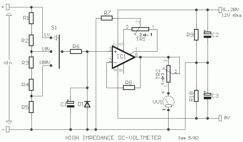
High Impedance DC Voltmeter using MOS Op-Amp
The circuit was designed to create a high-impedance voltmeter capable of measuring Direct Current (DC) voltages across various types of circuits.
The high-impedance voltmeter circuit typically employs operational amplifiers (op-amps) configured in a non-inverting arrangement to ensure minimal loading on the...
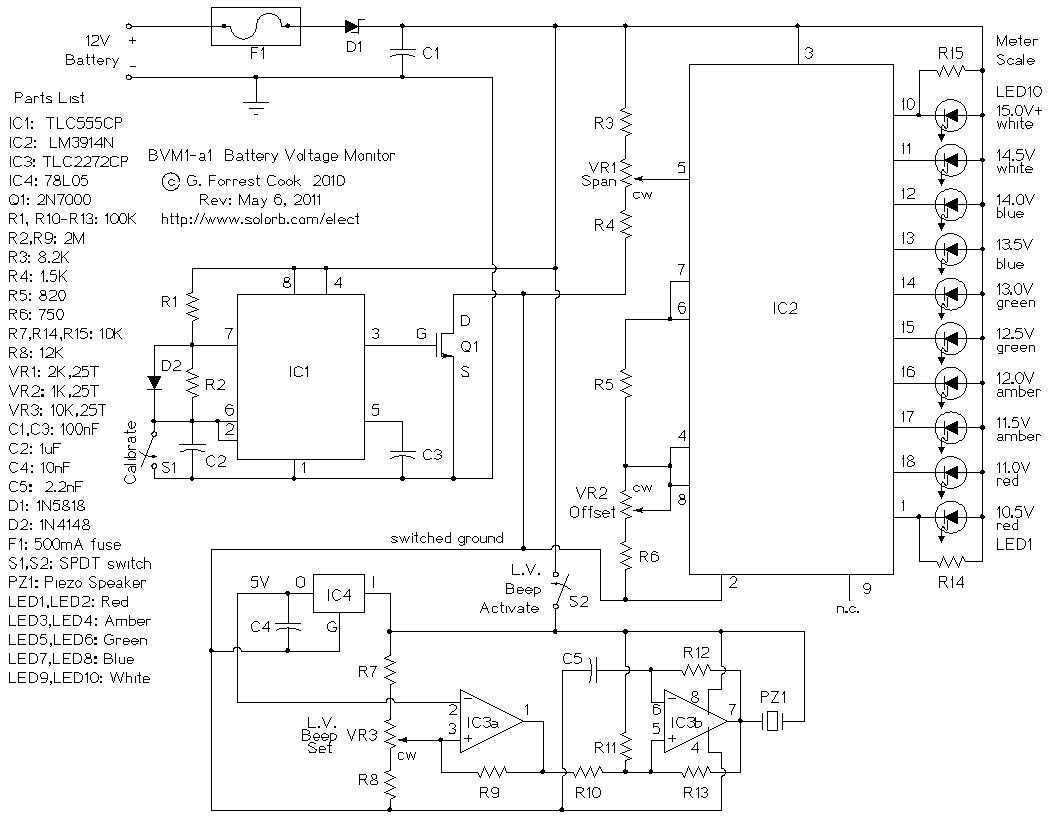
LED Voltmeter
This is a low power voltmeter circuit that can be used with alternative energy systems that run on 12 and 24 volt batteries. The voltmeter is an expanded scale type that indicates small voltage steps over the 10 to 16...
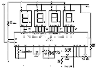
Digital voltmeter using ICL7107
The circuit presented is a highly effective and precise digital voltmeter with an LED display utilizing the ICL7107 from Intersil. The ICL7107 is a high-performance, low-power, 3.5-digit analog-to-digital converter (ADC). This integrated circuit (IC) incorporates internal components such as seven-segment...
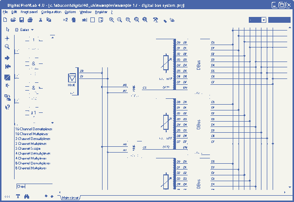
Digital-ProfiLab 4.0
Digital-ProfiLab was designed for measurement and control applications, combining features like circuit and logic simulation, front panel design, and hardware control to one powerful tool. Incoming signals from external devices may be processed and displayed. A circuit editor is used...
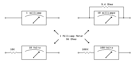
Analog Milliamp Meter Used as Voltmeter circuit
A milliamp meter can function as a voltmeter by incorporating a series resistance. The required resistance is calculated by dividing the full-scale voltage reading by the full-scale current of the meter movement. For instance, using a 1 milliamp meter to...
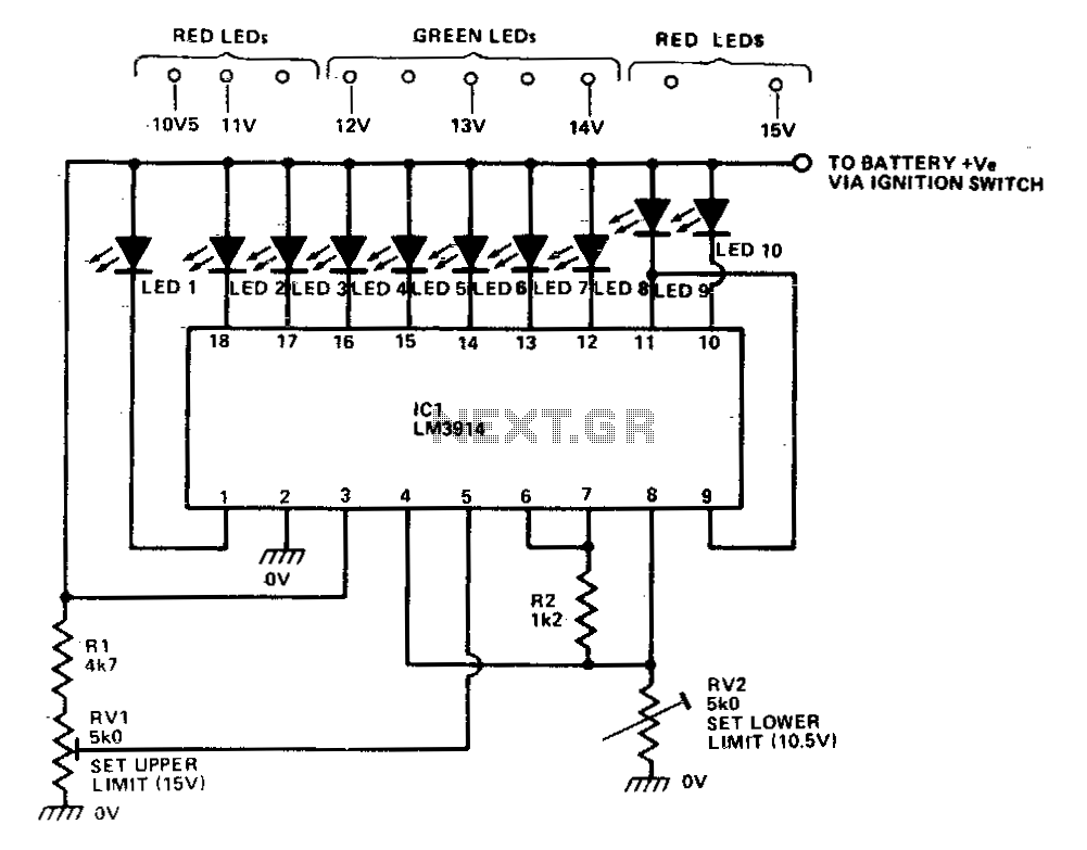
Bargrapk car voltmeter
The LM39X4 functions as a LED-driving voltmeter, with its maximum and minimum readings determined by the resistor values R2 and RV2. When properly calibrated, the device operates within a 2-volt to 3-volt range but is designed to read supply voltages...
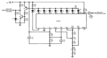
Constructing Voltmeter Monitor Circuit using LM3914
By utilizing several resistors, LEDs, and the LM3914 bar/dot display driver IC, it is possible to create a straightforward 5V voltmeter monitor circuit. This circuit offers TTL-compatible undervoltage and overvoltage warning signals. A complete circuit schematic is available below.
The described...
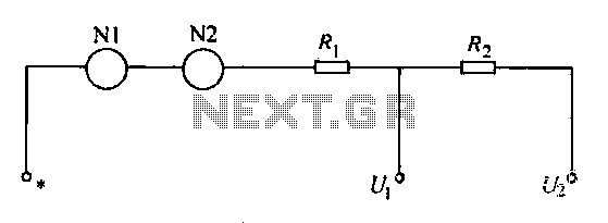
Table circuit voltage electric lines
A voltmeter operates through a measuring mechanism in a specified circuit, utilizing a moving coil in series with additional resistance. The fixed coil is denoted as N1, while the moving coil is designated as N2. The additional resistances are represented...
RealView 2.0
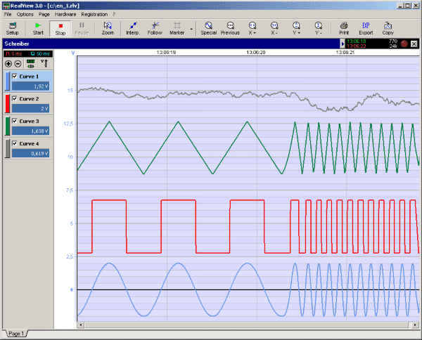
RealView is a measurement application, which records and plots measured values from analogue hardware devices in real-time. Several curves can be plotted into a single diagram. Several diagrams can be arranged on one or more pages if necessary. Plot options...