


speed control of dc motor
#ATMEL89C52
#DC motor
#speed control
#transistor
#optocoupler
#PWM
#duty cycle
#motor driver
#feedback control
#embedded systems
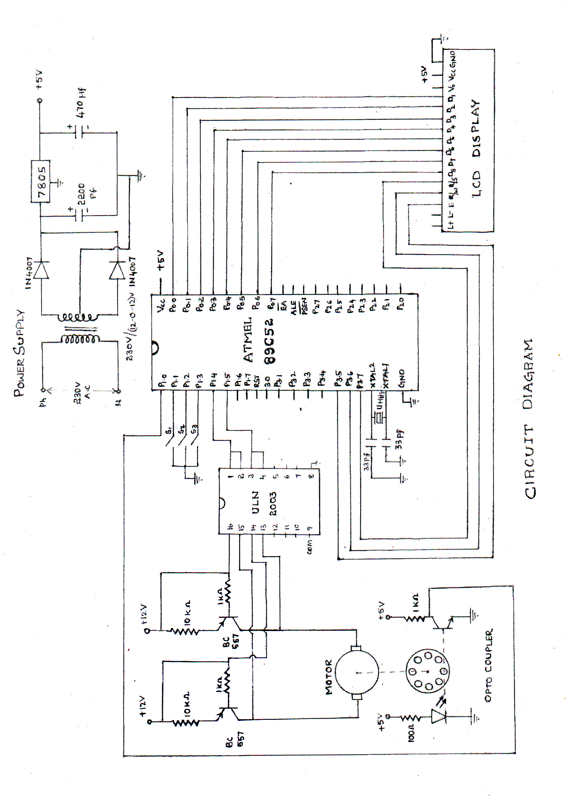
Description: The speed of the DC motor is controlled using an ATMEL89C52 microcontroller, with feedback provided by an optocoupler. The circuit diagram can be viewed above (click on the diagram for a larger view). The motor speed is regulated by employing a transistor as a control switch, where varying the duty cycle of the switching signal to the transistor adjusts the power supplied to the motor.
The circuit described utilizes an ATMEL89C52 microcontroller to manage the speed of a DC motor through pulse width modulation (PWM). This method allows for efficient control of the motor's speed by adjusting the average voltage supplied to the motor. The microcontroller generates a PWM signal, which is fed into a transistor acting as a switch. The transistor is configured to operate in saturation and cutoff regions, enabling it to turn on and off rapidly.
An optocoupler is employed in this circuit to provide feedback from the motor. The optocoupler isolates the microcontroller from the motor circuit, ensuring that any voltage spikes or noise generated by the motor do not affect the microcontroller's operation. The feedback signal from the optocoupler allows the microcontroller to monitor the actual speed of the motor, facilitating closed-loop control.
By varying the duty cycle of the PWM signal, the average voltage applied to the motor can be adjusted, thereby controlling its speed. A higher duty cycle results in more power delivered to the motor, increasing its speed, while a lower duty cycle decreases the power and slows the motor down. This method is efficient and allows for precise control of motor speed.
The schematic diagram associated with this circuit illustrates the connections between the microcontroller, transistor, optocoupler, and the DC motor. It is essential to ensure that the components are rated appropriately for the motor's voltage and current requirements to prevent damage. Additionally, proper heat sinking should be considered for the transistor if high currents are involved.speed of the d.c. motor is controlled by using ATMEL89C52 lmicrocontroller ,feedback from optocoupler. the circuit diagram can be seen above(click on the diagram to get larger view) the motor speed is controlled by the use of transistor as control switch varying the dutycycle of the switching signal to the transistor varies the power of..
The circuit described utilizes an ATMEL89C52 microcontroller to manage the speed of a DC motor through pulse width modulation (PWM). This method allows for efficient control of the motor's speed by adjusting the average voltage supplied to the motor. The microcontroller generates a PWM signal, which is fed into a transistor acting as a switch. The transistor is configured to operate in saturation and cutoff regions, enabling it to turn on and off rapidly.
An optocoupler is employed in this circuit to provide feedback from the motor. The optocoupler isolates the microcontroller from the motor circuit, ensuring that any voltage spikes or noise generated by the motor do not affect the microcontroller's operation. The feedback signal from the optocoupler allows the microcontroller to monitor the actual speed of the motor, facilitating closed-loop control.
By varying the duty cycle of the PWM signal, the average voltage applied to the motor can be adjusted, thereby controlling its speed. A higher duty cycle results in more power delivered to the motor, increasing its speed, while a lower duty cycle decreases the power and slows the motor down. This method is efficient and allows for precise control of motor speed.
The schematic diagram associated with this circuit illustrates the connections between the microcontroller, transistor, optocoupler, and the DC motor. It is essential to ensure that the components are rated appropriately for the motor's voltage and current requirements to prevent damage. Additionally, proper heat sinking should be considered for the transistor if high currents are involved.speed of the d.c. motor is controlled by using ATMEL89C52 lmicrocontroller ,feedback from optocoupler. the circuit diagram can be seen above(click on the diagram to get larger view) the motor speed is controlled by the use of transistor as control switch varying the dutycycle of the switching signal to the transistor varies the power of..
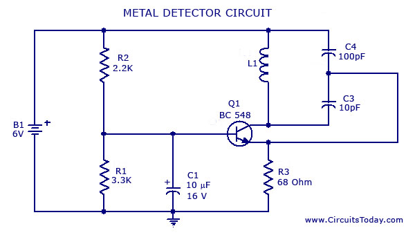
Metal Detector Circuit with Diagram and Schematic
A simple metal detector circuit diagram and schematic using a single transistor and a radio. This metal detector/sensor project is easy to make and is an application of a Colpitts oscillator.
The metal detector circuit utilizes a single transistor in conjunction...
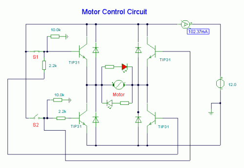
DC Motor Control Circuit
S1 and S2 are normally open, push-to-close, momentary switches. The diodes, which can be either red or green, serve solely to indicate the direction of operation. The TIP31 transistors may need to be adjusted based on the specifications of the...
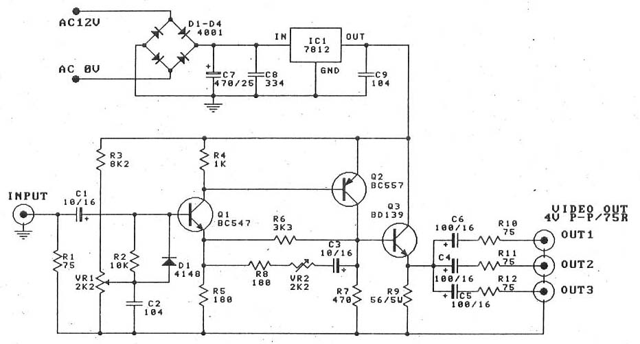
Video amplifier splitter by transistor BD137-BC547-BC557
This is a video amplifier circuit or video splitter circuit, designed to strengthen video signals. It compensates for signal loss and is...
The video amplifier circuit serves as a crucial component in video signal distribution systems, ensuring that the integrity and...

8 Channel software controlled fanbus with PWM
When discussing fan control, there are generally two methods: linear control and pulse-width modulation (PWM) control. Linear control is the most commonly used method, which involves reducing the voltage supplied to the fan. For a fan rated at 12 volts,...
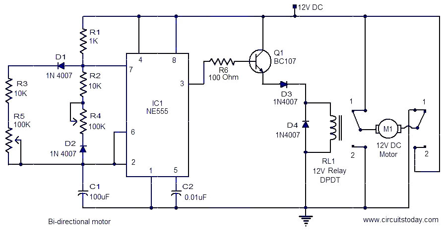
Bi-directional motor
This is a simple and easy-to-construct circuit designed to provide a bidirectional drive for a DC motor. The circuit operates straightforwardly. The output of an astable multivibrator based on IC1 (NE555) is utilized to control the relay RL1 that drives...
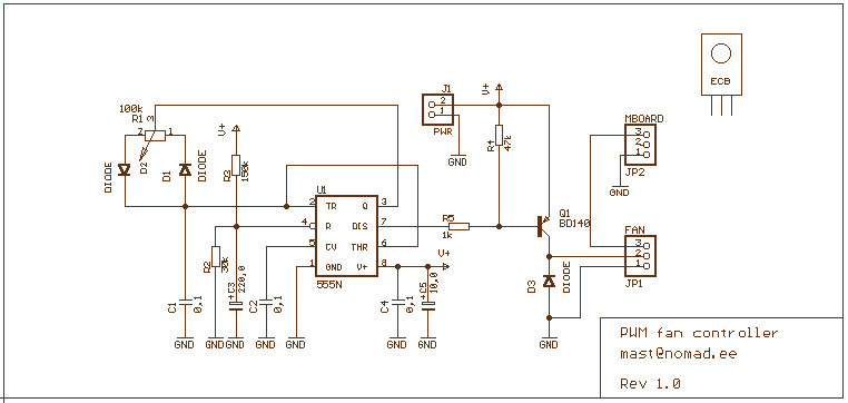
Simple PWM controller
This 555 timer based PWM controller features almost 0..100% pulse width regulation using R1, while keeping the oscillator frequency relatively stable. The frequency is dependent on values of R1 and C1, values shown will give a frequency range from about...
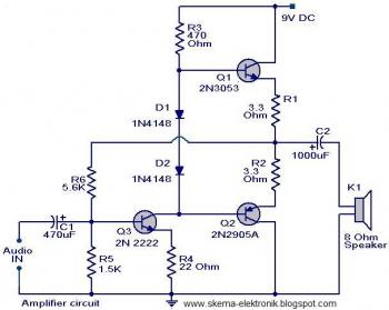
simple audio amplifier
The initial section of the circuit is a preamplifier that utilizes transistor Q1 (2N2222). The collector of transistor Q3 is connected to the base of transistor Q2 (2N2905A), which creates a complementary symmetry pair with Q3 (2N3053). The amplified signal...
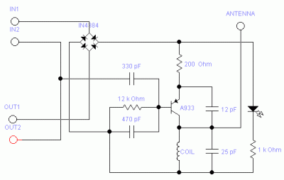
A933 Transistor Telephone Listening
The following circuit illustrates the A933 Transistor Telephone Listening Circuit Diagram. Features include the ability to tune from 88 to approximately 94 MHz and a simple design.
The A933 Transistor Telephone Listening Circuit is designed to function as a radio frequency...
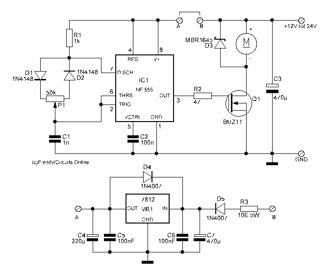
Motor Control circuit II
This circuit is 12 volt motors and lights well regulated. The scheme operates with PWM (Pulse Width Modulation). By IC1, a 555 is a square wave generated by a controllable duty cycle. This means that the width of the pulse...