


usb io
#PIC18F14k50
#USB
#digital I/O
#microcontroller
#programmable
#DIP20
#SMD
#USB host
#12-bit
#I/O extender
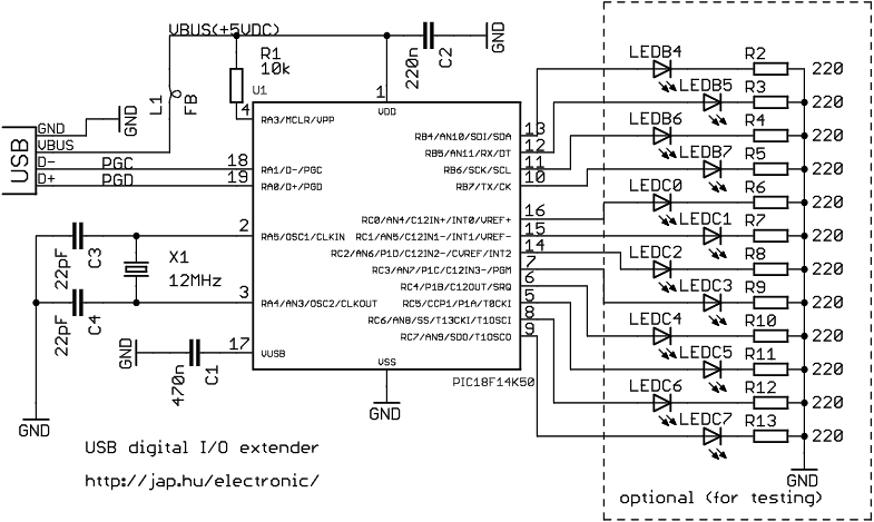
Description: This project is a 12-bit digital I/O extender utilizing the Microchip PIC18F14K50 microcontroller, which connects to a USB host port. The microcontroller is available in both through-hole DIP20 and SMD packages. It is important to note that the PIC18F14K50 is a general-purpose microcontroller that must be programmed before use in an actual circuit. The device is powered by the USB bus. Ports RB4-7 and RC0-7 can be configured individually for input or output direction. All LEDs in the schematic are optional and are included solely for testing purposes. The USB connector pinouts can be referenced for connection details. A computer or an embedded RISC board with a USB host port can control the I/O extender. The provided controlio example code utilizes libusb, eliminating the need for a kernel driver for interfacing. The circuit operates as a full-speed (12 Mbit) vendor-specific USB device, utilizing only control endpoint 0 and governed by vendor-specific control requests. A package/usbio/Makefile is under development (not yet available, but inquiries can be made if needed). Files from the usbio.zip c/ directory should be copied to the SDK package/usbio/src/ for further implementation.
The 12-bit digital I/O extender project leverages the capabilities of the Microchip PIC18F14K50 microcontroller to create a versatile interface for digital input and output applications. This microcontroller, designed for ease of use, is suitable for both hobbyists and professionals, given its availability in multiple package types, such as DIP20 and SMD, facilitating integration into various circuit designs.
The device operates by being powered through the USB bus, ensuring a straightforward power supply mechanism that is commonly available in modern electronic environments. The configuration of the I/O ports—RB4-7 and RC0-7—allows for flexible operation, permitting the user to set each port individually to function as either an input or output. This feature is particularly beneficial in applications requiring dynamic control of digital signals.
The schematic includes optional LEDs, which serve as visual indicators for testing the device's functionality. These components can be omitted in final designs, streamlining the circuit for production if desired. The USB connector pinouts are critical for establishing the connection between the I/O extender and the controlling device, be it a computer or an embedded RISC board equipped with a USB host port.
The controlio example code, which utilizes the libusb library, simplifies the process of interfacing with the device. This approach negates the necessity for a kernel driver, making it accessible for users who may not have extensive experience with driver development. The device operates as a full-speed USB device at 12 Mbit, utilizing control endpoint 0 for communication. This design choice ensures efficient data transfer while maintaining compatibility with a wide range of USB host devices.
For those looking to develop custom host interfaces, the project documentation indicates that vendor-specific control requests have been implemented, allowing for tailored interactions with the I/O extender. The ongoing development of the package/usbio/Makefile indicates active project maintenance, with resources available for users who wish to further explore or contribute to the project. Users are encouraged to copy the necessary files from the provided usbio.zip archive to the designated SDK directory to facilitate their development efforts.This project is a 12-bit digital I/O extender using the Microchip PIC18f14k50 microcontroller which connects to an USB host port. The microcontroller is available in through-hole DIP20 and SMD packages, too. NOTE for beginners: PIC18F14k50 is a general purpose microcontrollerwhich has to be programmed before you can use it in the actual circuit.
Please check out this link to learn more. The device is powered by the USB bus. The ports RB4-7, RC0-7 can be set on a bit-by-bit basis to input or output direction. All LEDs on the schematic are optional, and are only shown for testing the device. You can find the USB connector pinouts at A computer or an embedded RISC board with an USB host port can be used to control the I/O extender. The controlio example code uses libusb. This means that you don`t need a kernel driver to interface with it. The circuit is a full speed (12Mbit) vendor-specific USB device. It uses only the control endpoint 0, and is controlled by vendor-specific control requests. If you want to make your own host interface, the implemented control requests are: - a package/usbio/Makefile is being made (not yet ready, please ask for it if you need).
Copy files from usbio. zip c/ directory to the SDK package/usbio/src/
The 12-bit digital I/O extender project leverages the capabilities of the Microchip PIC18F14K50 microcontroller to create a versatile interface for digital input and output applications. This microcontroller, designed for ease of use, is suitable for both hobbyists and professionals, given its availability in multiple package types, such as DIP20 and SMD, facilitating integration into various circuit designs.
The device operates by being powered through the USB bus, ensuring a straightforward power supply mechanism that is commonly available in modern electronic environments. The configuration of the I/O ports—RB4-7 and RC0-7—allows for flexible operation, permitting the user to set each port individually to function as either an input or output. This feature is particularly beneficial in applications requiring dynamic control of digital signals.
The schematic includes optional LEDs, which serve as visual indicators for testing the device's functionality. These components can be omitted in final designs, streamlining the circuit for production if desired. The USB connector pinouts are critical for establishing the connection between the I/O extender and the controlling device, be it a computer or an embedded RISC board equipped with a USB host port.
The controlio example code, which utilizes the libusb library, simplifies the process of interfacing with the device. This approach negates the necessity for a kernel driver, making it accessible for users who may not have extensive experience with driver development. The device operates as a full-speed USB device at 12 Mbit, utilizing control endpoint 0 for communication. This design choice ensures efficient data transfer while maintaining compatibility with a wide range of USB host devices.
For those looking to develop custom host interfaces, the project documentation indicates that vendor-specific control requests have been implemented, allowing for tailored interactions with the I/O extender. The ongoing development of the package/usbio/Makefile indicates active project maintenance, with resources available for users who wish to further explore or contribute to the project. Users are encouraged to copy the necessary files from the provided usbio.zip archive to the designated SDK directory to facilitate their development efforts.This project is a 12-bit digital I/O extender using the Microchip PIC18f14k50 microcontroller which connects to an USB host port. The microcontroller is available in through-hole DIP20 and SMD packages, too. NOTE for beginners: PIC18F14k50 is a general purpose microcontrollerwhich has to be programmed before you can use it in the actual circuit.
Please check out this link to learn more. The device is powered by the USB bus. The ports RB4-7, RC0-7 can be set on a bit-by-bit basis to input or output direction. All LEDs on the schematic are optional, and are only shown for testing the device. You can find the USB connector pinouts at A computer or an embedded RISC board with an USB host port can be used to control the I/O extender. The controlio example code uses libusb. This means that you don`t need a kernel driver to interface with it. The circuit is a full speed (12Mbit) vendor-specific USB device. It uses only the control endpoint 0, and is controlled by vendor-specific control requests. If you want to make your own host interface, the implemented control requests are: - a package/usbio/Makefile is being made (not yet ready, please ask for it if you need).
Copy files from usbio. zip c/ directory to the SDK package/usbio/src/
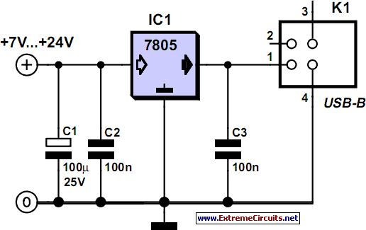
Power Supply For USB Devices
An increasing number of devices operate on internal rechargeable batteries. While a compatible charger is typically included, some devices can only be charged via a USB port. This is common with USB MP3 players, which require docking with a PC...
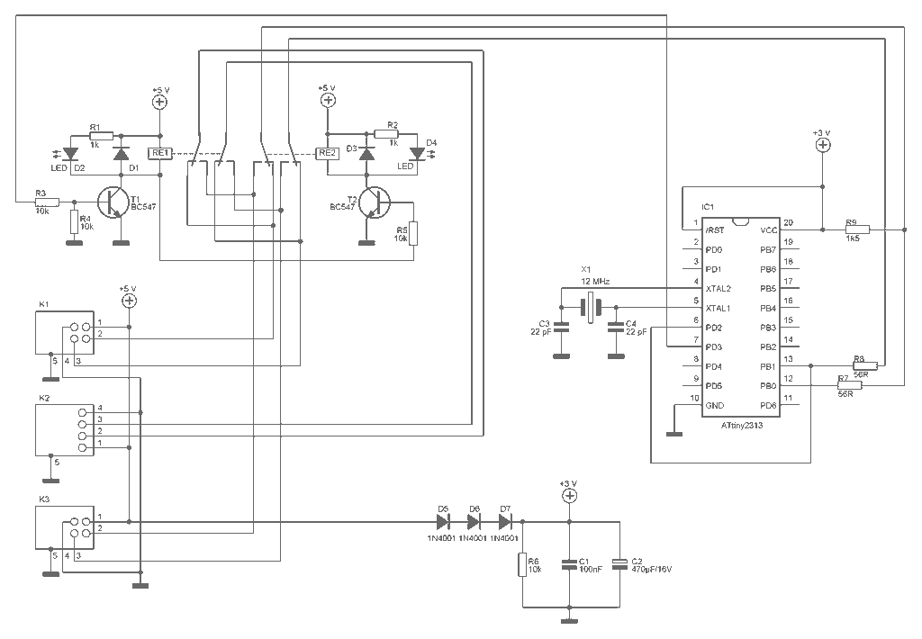
USB selector switch
To share a regional press like the USB printer, scanner etc. two computers, it is relatively easy. Just connect the two computers on a network device and say the printer as shared. This method however requires the continued operation of...
usb
This document outlines a project completed by a team between September 2000 and March 2001 as part of the Engineering Physics degree program at the University of British Columbia. The project involved constructing a USB device utilizing the PIC 16C745...
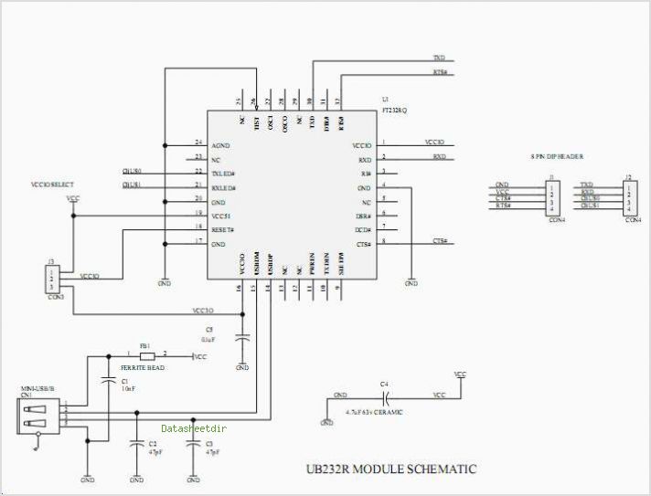
Ub232r Usb Mini-b Ft232r Evaluation Module
The UDA1343TT is a single-chip stereo analog-to-digital converter (ADC) and digital-to-analog converter (DAC) that features basic signal processing capabilities using bitstream conversion techniques. Its low power consumption, compact package size, and low voltage requirements make it highly suitable for low-voltage,...
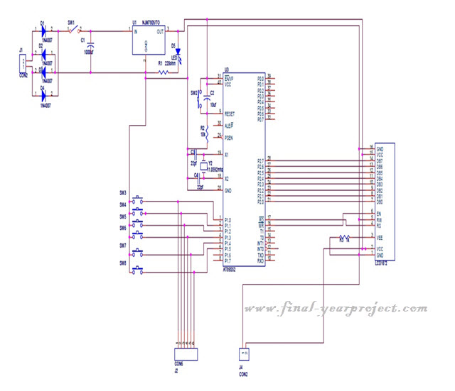
Microcontroller based College Automation System
This project is a microcontroller-based college automation system aimed at addressing the challenges faced in educational institutions. It replaces the conventional notice board with an automated device that allows users to both hear and read the information being announced through...
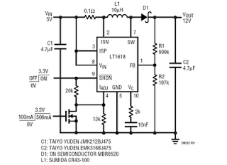
usb-voltage-converter-5v-to-12v.html
This is a 5V to 12V DC-DC step-up (boost) converter circuit designed specifically for USB-powered applications. A USB port has two current supply modes. Initially, it supplies a maximum of 100mA to the load before detecting the connected device. Once...
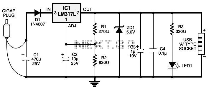
Car Cigar Lighter to USB Power Socket
Currently, nearly all computer systems include logic blocks designed for interfacing with a USB port. In practical terms, a USB port can provide more than 100 mA of continuous electric current at 5V to the peripherals connected to the bus.
The...
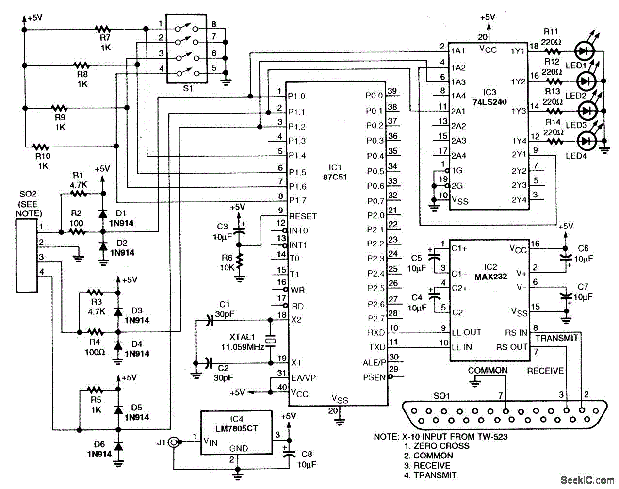
POWER LINE MODEM FOR COMPUTER CONTROL
This circuit employs an 87C57 microcontroller along with several peripherals to convert X-10 power-line carrier-code formats from a personal computer for use with an X-10 power-line interface in a home-control system. Software details can be found in the reference.
The circuit...
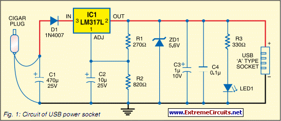
Usb Power Socket With Indicator circuit
Today, nearly all computers are equipped with logic blocks designed to implement a USB port. In practice, a USB port can deliver over 100 mA of continuous current at 5V to the peripherals connected to the bus. This capability allows...