


using programming pods at the in circuit test stage
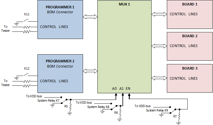
Description: The use of programming pods has become a standard practice in manufacturing, particularly during the early development stages of firmware for new products. Once visual and structural tests are completed, the board is prepared for full functional testing. The in-circuit test (ICT) station serves as the optimal location for programming an electronic board for several reasons. In a recent project, a customer requested the programming of a panelized board, where each board contained two different programmable devices. To address this, two programming pods (P&E Micro Cyclone Pro programming adapters) were utilized along with multiplexers. This project faced multiple challenges, which were resolved by employing two multiplexer boards controlled through the ICT program. Each multiplexer managed the programming of three boards, given that there were six boards in total per panel. The Cyclone Pro programmers are user-friendly; once the firmware is loaded, the operator simply presses the START button and monitors the SUCCESS and ERROR LEDs. To automate this process, control lines for the START button, SUCCESS, and ERROR LEDs were wired to the ICT machine, allowing the ICT program to manage the process without operator intervention. Following the START command, the test program monitors the two LEDs for results. If the SUCCESS LED illuminates, the test program displays a Programming PASS message; otherwise, it indicates a Programming FAIL. Additionally, to facilitate the uploading of the latest firmware into the programming pods, the test fixture included two USB connectors, each linked to one of the programming pods. This configuration enables a test engineer to efficiently upload newly released firmware through the USB bus to the pods.
The described circuit utilizes a dual programming pod setup, specifically the P&E Micro Cyclone Pro, which is designed for ease of use in a manufacturing environment. The integration of multiplexers allows for simultaneous programming of multiple boards, enhancing efficiency. The multiplexers are controlled by an in-circuit test program, which facilitates automation and reduces the need for manual intervention by operators.
The design includes control lines that connect the START button and LED indicators (SUCCESS and ERROR) directly to the ICT machine. This connection allows the ICT program to execute commands and monitor the programming process in real-time. The inclusion of the USB connectors in the test fixture provides a straightforward method for firmware updates, ensuring that the programming pods can be easily maintained and kept up-to-date with the latest software versions.
The overall architecture of this programming solution is aimed at minimizing downtime and maximizing throughput during the manufacturing process. By automating the programming sequence and integrating user-friendly interfaces, the system ensures reliable performance and simplifies the workflow for test engineers. The use of multiplexers not only addresses the challenges posed by panelized boards but also optimizes resource usage by allowing multiple boards to be programmed concurrently. This design exemplifies modern practices in electronic manufacturing and testing, highlighting the importance of automation and efficiency in the production of electronic devices.Nowadays using programming pods are commonly accepted and widely used in manufacturing, especially when a new product is introduced and the firmware is in the early development stages. After the completion of all visual and structure tests, the board is ready for full functional test. The in-circuit test station is the best point for programming a n electronic board for the following reasons: In a recent project, a customer asked to program a panelized board. Each board has two different programmable devices. Our approach was to use two programming pods (P&E Micro Cyclone Pro programming adapter) with multiplexers.
This project presented all four of the difficulties listed above. In order to overcome the panelized board issue, we decided to use two multiplexer boards which were being controlled through the in-circuit test program. Since there were six boards in each panel, each multiplexer was responsible for programming three boards.
Cyclone Pro programmers are very easy to use. As soon as the firmware is loaded, the user only needs to press the START button and monitor SUCCESS and ERROR LEDs. In order to automate the process, we decided to wire the above mentioned control lines (START button, SUCCESS and ERROR LEDs) to the ICT machine, so controlling the process would be through the ICT program and the operator will have no intervention.
After sending START command, the test program monitors two LEDs for the result. If SUCCESS LED turns on, the test program will send a Programming PASS message to the screen, otherwise the result is a fail and the screen will show Programming FAIL . In order to be able to upload the latest firmware into the programming pods, the test fixture incorporated 2 USB connectors, each of which was connected to one of the programming pods.
This allows a test engineer to quickly and easily upload a newly released firmware through the USB bus to the pods.
The described circuit utilizes a dual programming pod setup, specifically the P&E Micro Cyclone Pro, which is designed for ease of use in a manufacturing environment. The integration of multiplexers allows for simultaneous programming of multiple boards, enhancing efficiency. The multiplexers are controlled by an in-circuit test program, which facilitates automation and reduces the need for manual intervention by operators.
The design includes control lines that connect the START button and LED indicators (SUCCESS and ERROR) directly to the ICT machine. This connection allows the ICT program to execute commands and monitor the programming process in real-time. The inclusion of the USB connectors in the test fixture provides a straightforward method for firmware updates, ensuring that the programming pods can be easily maintained and kept up-to-date with the latest software versions.
The overall architecture of this programming solution is aimed at minimizing downtime and maximizing throughput during the manufacturing process. By automating the programming sequence and integrating user-friendly interfaces, the system ensures reliable performance and simplifies the workflow for test engineers. The use of multiplexers not only addresses the challenges posed by panelized boards but also optimizes resource usage by allowing multiple boards to be programmed concurrently. This design exemplifies modern practices in electronic manufacturing and testing, highlighting the importance of automation and efficiency in the production of electronic devices.Nowadays using programming pods are commonly accepted and widely used in manufacturing, especially when a new product is introduced and the firmware is in the early development stages. After the completion of all visual and structure tests, the board is ready for full functional test. The in-circuit test station is the best point for programming a n electronic board for the following reasons: In a recent project, a customer asked to program a panelized board. Each board has two different programmable devices. Our approach was to use two programming pods (P&E Micro Cyclone Pro programming adapter) with multiplexers.
This project presented all four of the difficulties listed above. In order to overcome the panelized board issue, we decided to use two multiplexer boards which were being controlled through the in-circuit test program. Since there were six boards in each panel, each multiplexer was responsible for programming three boards.
Cyclone Pro programmers are very easy to use. As soon as the firmware is loaded, the user only needs to press the START button and monitor SUCCESS and ERROR LEDs. In order to automate the process, we decided to wire the above mentioned control lines (START button, SUCCESS and ERROR LEDs) to the ICT machine, so controlling the process would be through the ICT program and the operator will have no intervention.
After sending START command, the test program monitors two LEDs for the result. If SUCCESS LED turns on, the test program will send a Programming PASS message to the screen, otherwise the result is a fail and the screen will show Programming FAIL . In order to be able to upload the latest firmware into the programming pods, the test fixture incorporated 2 USB connectors, each of which was connected to one of the programming pods.
This allows a test engineer to quickly and easily upload a newly released firmware through the USB bus to the pods.
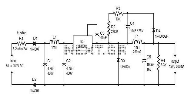
Power supplies for microcontroller based projects
This document discusses the use of small microcontrollers, such as those from the PIC and Atmel series, which typically operate at 5V and require less than 100mA for complete system functionality. Some PICs can function at lower voltages, such as...
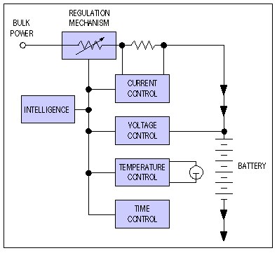
How to Design Battery Charger Applications that Require External Microcontrollers and Related System-Level Issues
Application note on designing linear and switch-mode (switching DC-DC converter current source) battery charger applications that require external microcontrollers and related system-level issues for notebook computers.
The application note provides guidance on the design of both linear and switching DC-DC converter...
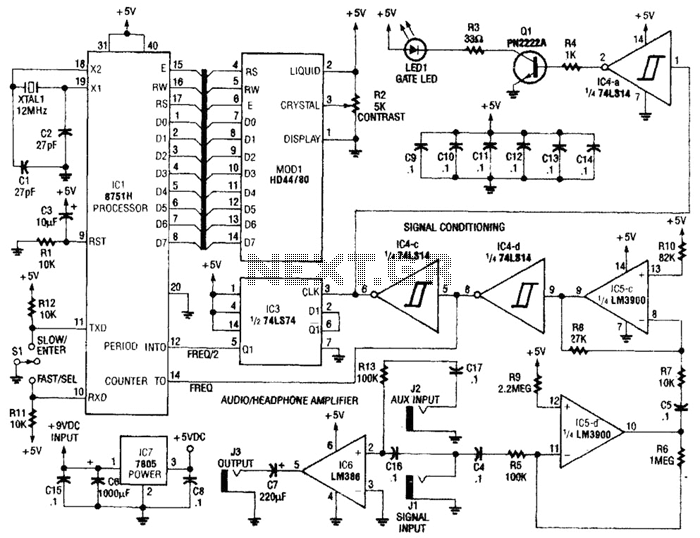
Perfect Pitch Circuit
Perfect Pitch, which is based on the 8751 microprocessor, is an affordable and straightforward instrument tuner and frequency counter that features a built-in headphone amplifier and a visual metronome. Perfect Pitch converts the audio signal from an instrument into a...
delay
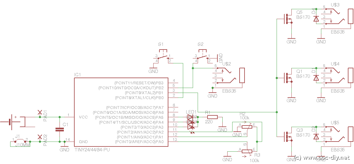
This article outlines the construction of a simple microcontroller-based delay circuit designed for photographic applications, such as drop or high-speed photography. It is capable of controlling the trigger lag for cameras and flash units, generating periodic trigger pulses, or managing...
mosfet Turning a microcontroller on with a flip flop
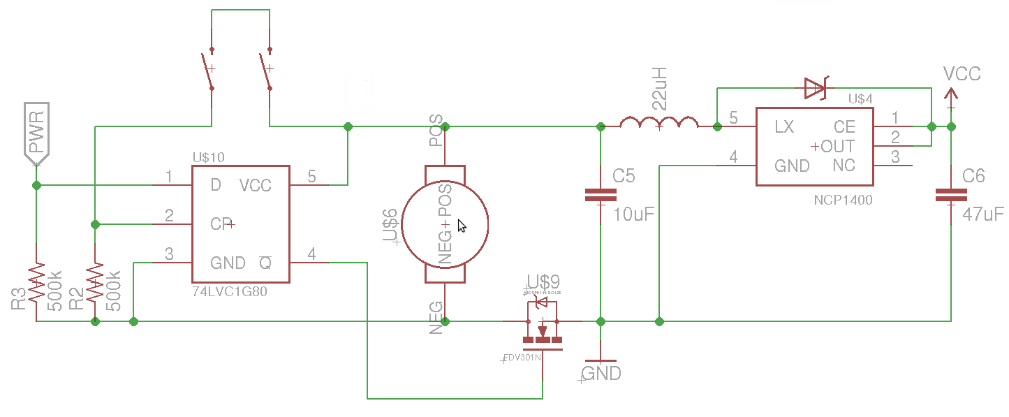
The objective is to control the power to a load, specifically an 8051-based microcontroller (uC), using two switches. When the uC is powered on, it sets the PWR pin high. Upon pressing the switches again, pin 4 of the flip-flop...
Microcontroller based College Automation System
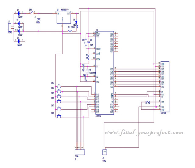
This project is a microcontroller-based college automation system aimed at addressing the challenges faced in educational institutions. It replaces the conventional notice board with an automated device that allows users to both hear and read the information being announced through...
MICROCONTROLLER BASED AUTOMATIC ROOM LIGHT CONTROLLER
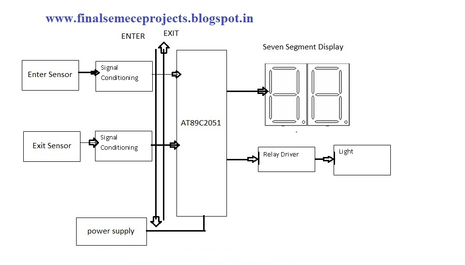
This project involves an automatic room light controller with a bidirectional visitor counter using a microcontroller. It is designed to manage room lighting and accurately count the number of individuals present. When a person enters the room, the counter increments...
87C51 Selling Leads
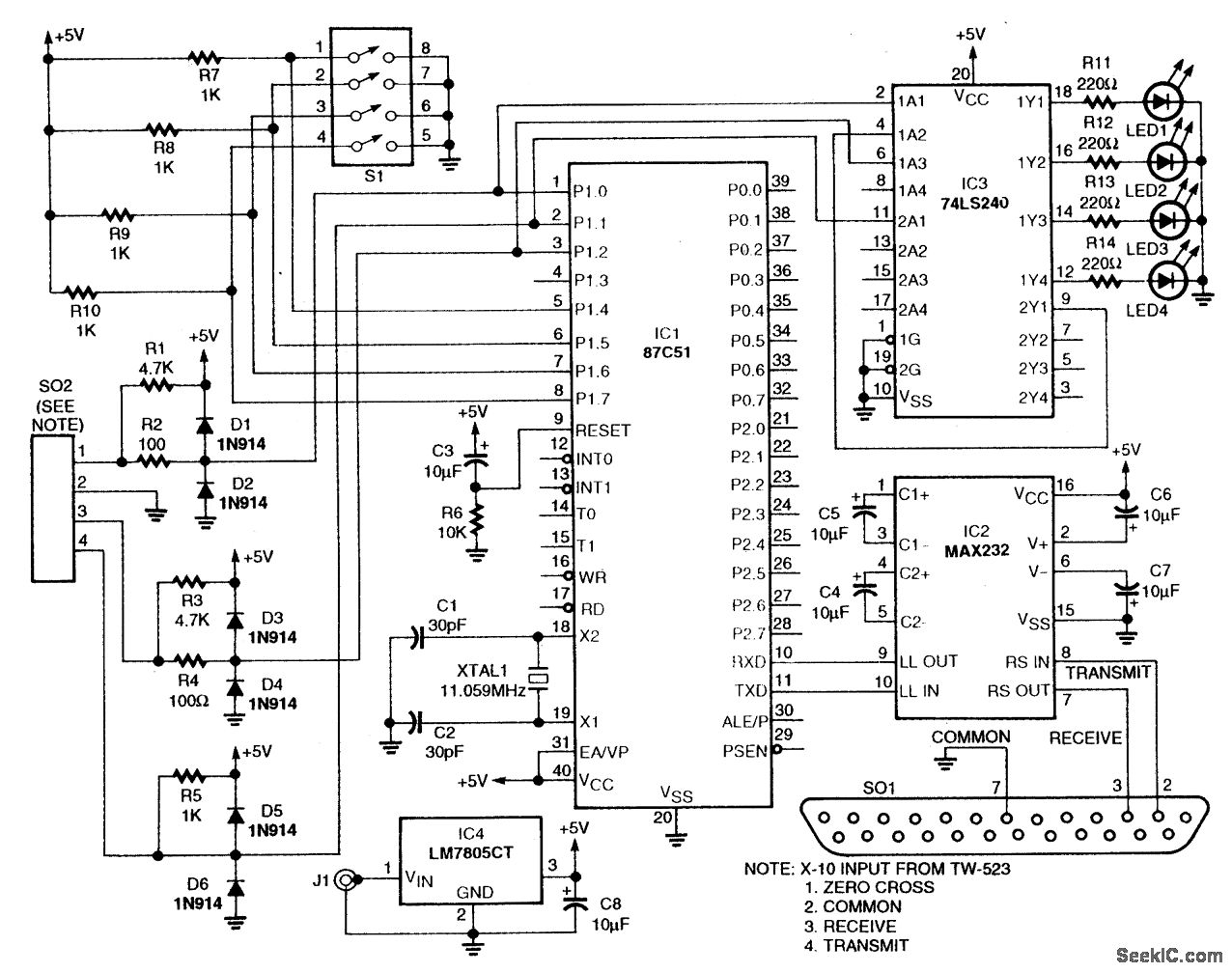
This circuit utilizes an 87C57 microcontroller along with several peripherals to convert X-10 power-line carrier-code formats from a personal computer for use with an X-10 power-line interface in a home control system. Software details can be found in the reference....
Interactive Voice Response System
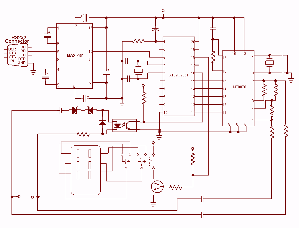
Nowadays every institution needs automation. As a part of college automation, a project has been developed for a Voice Interactive System for College Automation. This project allows users to quickly access student attendance and marks through the telephone line without...