


What transistor to use when building a simple MCU controlled LED blinking circuit
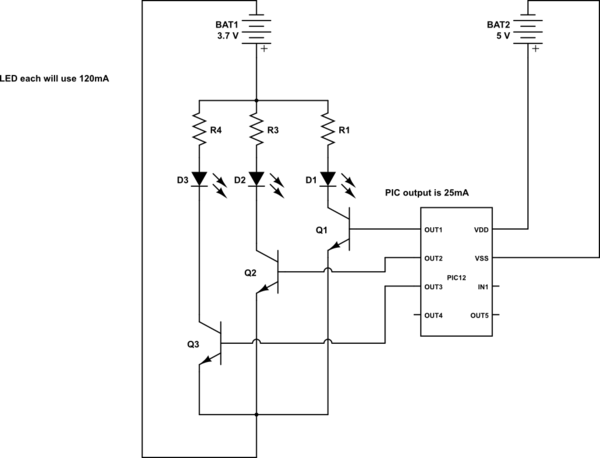
Description: This is a conceptual schema utilizing a PIC12 microcontroller to control the blinking of three LEDs, each exhibiting different blinking patterns. There are several questions that need to be addressed.
The circuit design involves a PIC12 microcontroller, which is a compact and efficient device suitable for controlling simple tasks such as LED blinking. The microcontroller will be programmed to generate distinct timing sequences for each of the three LEDs, allowing for varied blinking patterns.
The schematic will include the following components:
1. **Microcontroller (PIC12)**: The central processing unit that executes the blinking patterns. It will be powered by a suitable voltage source, typically 5V DC.
2. **LEDs**: Three individual light-emitting diodes, each connected to a different output pin of the PIC12. Resistors will be included in series with each LED to limit the current and prevent damage. The values of these resistors should be calculated based on the LED specifications and the supply voltage.
3. **Resistors**: Each LED will require a current-limiting resistor, calculated using Ohm's Law. For example, if an LED has a forward voltage of 2V and a desired current of 20mA, a resistor value of approximately 150 ohms would be appropriate when using a 5V supply.
4. **Programming Interface**: To load the blinking pattern program onto the PIC12, a programming interface (such as ICSP - In-Circuit Serial Programming) may be included in the schematic. This allows for easy updates to the microcontroller's firmware.
5. **Power Supply**: A stable power source will be required to ensure consistent operation of the microcontroller and LEDs. This can be a battery or a regulated power supply, providing the necessary voltage and current.
The blinking patterns for the LEDs can be programmed using a simple loop structure in the firmware. Different delays can be implemented to achieve various blinking effects, such as alternating flashes, simultaneous blinking, or sequential lighting.
Overall, this circuit provides a straightforward yet effective means of demonstrating microcontroller capabilities in controlling multiple outputs with varying behaviors. The design can be expanded or modified to include additional features such as user inputs or more complex patterns as needed.This is my conceptual schema to use a PIC12 to control the blinking of 3 LEDs with different blinking patterns. I have a few questions that would like to ask.
The circuit design involves a PIC12 microcontroller, which is a compact and efficient device suitable for controlling simple tasks such as LED blinking. The microcontroller will be programmed to generate distinct timing sequences for each of the three LEDs, allowing for varied blinking patterns.
The schematic will include the following components:
1. **Microcontroller (PIC12)**: The central processing unit that executes the blinking patterns. It will be powered by a suitable voltage source, typically 5V DC.
2. **LEDs**: Three individual light-emitting diodes, each connected to a different output pin of the PIC12. Resistors will be included in series with each LED to limit the current and prevent damage. The values of these resistors should be calculated based on the LED specifications and the supply voltage.
3. **Resistors**: Each LED will require a current-limiting resistor, calculated using Ohm's Law. For example, if an LED has a forward voltage of 2V and a desired current of 20mA, a resistor value of approximately 150 ohms would be appropriate when using a 5V supply.
4. **Programming Interface**: To load the blinking pattern program onto the PIC12, a programming interface (such as ICSP - In-Circuit Serial Programming) may be included in the schematic. This allows for easy updates to the microcontroller's firmware.
5. **Power Supply**: A stable power source will be required to ensure consistent operation of the microcontroller and LEDs. This can be a battery or a regulated power supply, providing the necessary voltage and current.
The blinking patterns for the LEDs can be programmed using a simple loop structure in the firmware. Different delays can be implemented to achieve various blinking effects, such as alternating flashes, simultaneous blinking, or sequential lighting.
Overall, this circuit provides a straightforward yet effective means of demonstrating microcontroller capabilities in controlling multiple outputs with varying behaviors. The design can be expanded or modified to include additional features such as user inputs or more complex patterns as needed.This is my conceptual schema to use a PIC12 to control the blinking of 3 LEDs with different blinking patterns. I have a few questions that would like to ask.
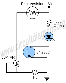
light activated led
This project involves a simple and engaging light-activated LED circuit that illuminates an LED in response to light exposure. The circuit is straightforward to construct, requiring only six components. A photoresistor is utilized for light sensing, while a 2N2222 transistor...
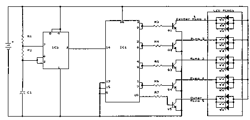
98 LEDs Fantastic Atom Expander
Here is the schematic, PC board pattern, and parts placement for a "Fantastic Atom Expander". This circuit produces an "exploding atom" effect using 98 LEDs. The LEDs can be any colour but blue. For a very interesting effect, make one...
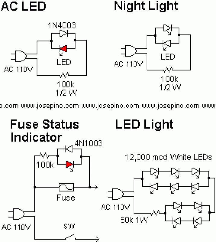
How to connect LED's directly to MAINS
A LED is defined as "light-emitting diode: diode such that light emitted at a p-n junction is proportional to the bias current; color depends on the material used." As the LED is a diode, it doesn't conduct electricity in both...
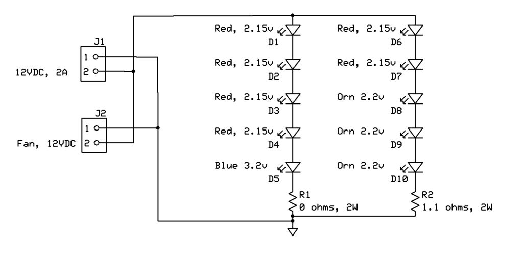
High-Brightness LED Grow-Light
This project page has evolved into a design discussion. Constructive suggestions and collaboration are still welcome. Please refer to the comments section.
The project focuses on the development of an electronic circuit design, which has transitioned from a simple project overview...
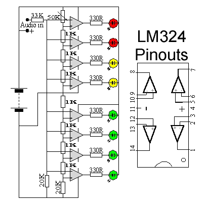
LED Audio Level Meter Circuit Schematic Diagram
This circuit utilizes two quad op-amps to create an eight LED audio level meter. The op-amp employed in this circuit is the LM324, a widely used integrated circuit that is readily available from numerous electronic component suppliers. The 1K resistors...
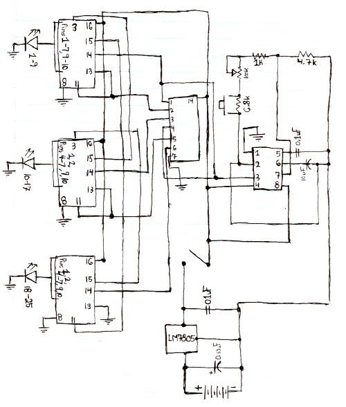
Rotating LED Marquee Hat circuit
Here is the schematic for the circuit. Solder all the components onto a perfboard. The drawings may not be very clear. Essentially, the 555 timer generates a pulse.
The circuit utilizes a 555 timer IC configured in astable mode, which allows...
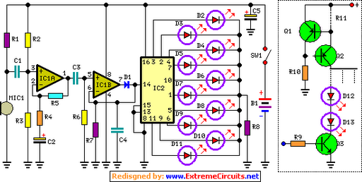
Dancing LEDs
The basic circuit illuminates up to ten LEDs in sequence, synchronized with the rhythm of music or speech detected by a small microphone. The expanded version can drive up to ten strips, each consisting of up to five LEDs, powered...
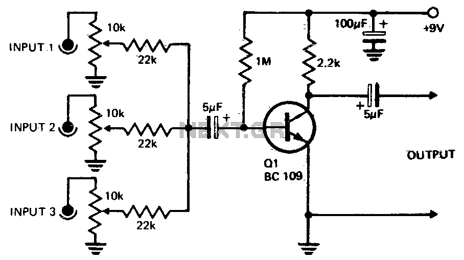
One transistor audio mixer
Three or more inputs with individual level controls feed into the base of Q1, which provides a voltage gain of 20.
The circuit design involves a transistor amplifier configuration where three or more input signals are managed through individual level control...
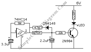
Blinking LED Emulates Incandescent Bulb
This circuit features a flashing LED that emulates the behavior of an incandescent lamp. The characteristic of an incandescent lamp is that it cannot abruptly change its brightness.
The flashing LED circuit designed to mimic an incandescent lamp operates by simulating...