


agriculture based robot e project
#agriculture robot
#prototype
#automation
#farming
#labor shortage
#sensors
#motor control
#educational
#arduino
#home automation
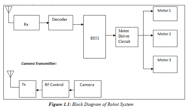
Description: A prototype model of an agriculture-based robot has been developed to address the challenges faced by farmers who have traditionally relied on manual labor for cultivating their lands. The increasing urbanization has led to a shortage of labor, as younger individuals are drawn to city life and job opportunities. This agricultural robot aims to alleviate the labor shortage problem. The block diagram of the agriculture-based robot consists of a Microcontroller Unit (P89V51RD2), an IC, an RS-232 port, a keypad, a TV, a wireless camera, motors, and a driver circuit. The system functions as a receiver, incorporating a receiving antenna, a receiver, a decoder, an 8051 microcontroller IC, a motor driver circuit, and motors. The signals received by the antenna are processed by the receiver and decoded for further action. The motor driver circuit, in conjunction with the 8051 microcontroller, controls all motors.
The camera transmitter includes a camera, an RF controller, a transmitter, and a transmitting antenna. The camera captures images, which are converted into RF signals for transmission. This unit also manages the spraying actions and other functionalities of the robot.
Step 1: The robot allows farmers to control it remotely from their homes, enabling them to view their fields through the camera, which provides clear images and sound.
Step 2: The robot can spray pesticides or water over extensive areas of the field using a submersible pump for efficient distribution.
Step 3: The robot's movements—right, left, forward, and reverse—are controlled via the transmitter and receiver, with actions initiated by pressing the keypad. This capability allows users to maneuver the robot in challenging areas with ease.
The agriculture-based robot is designed to enhance efficiency in farming practices by automating tasks traditionally performed by human laborers. The integration of the P89V51RD2 microcontroller serves as the central processing unit, coordinating various components of the system. The RS-232 port facilitates communication between the robot and external devices, while the keypad allows for user input to control the robot's movement and functions.
The wireless camera system offers real-time monitoring of the fields, transmitting video signals to the user’s display unit. This feature is crucial for assessing crop health and monitoring irrigation needs without the necessity of physical presence in the fields.
The motor driver circuit is an essential component that translates the microcontroller's commands into physical movement, enabling the robot to navigate complex terrains. The use of a submersible pump for pesticide and water spraying ensures that the robot can efficiently cover large areas, improving the overall productivity of the farming operations.
In summary, the agriculture-based robot represents a significant advancement in agricultural technology, providing a solution to labor shortages and enhancing the efficiency of farming practices through automation and remote control capabilities.A prototype model of Agriculture Based Robot . Till recently the farmers were using age-old instruments in cultivating their lands. They themselves were putting the manuallabor. Hence there was thelabor problem. Farmer`s facing this type oflaborshortage. Because, now the youngsters are attracted by the city life & jobs in the towns. The farmer`s struggled from thislaborerproblem. figure 1. 1 and figure 1. 2 shows the implementation block diagram of The Agriculture Based Robot . The block diagram consists of Microcontroller Unit ( P89V51RD2), IC, RS-232 port, Key-pad, TV, Wireless Camera, Motors &driver circuit, etc. It is nothing but a receiver. This unit consists of receiving antenna, receiver, decoder, 8051microcontroller IC, motor driver circuit & motors.
Here the signal is received from the antenna and goes to receiver. Then we can decode signal with the use of decoder. All motors are controlled by the motor driver circuit & with the help of 8051microcontroller. Camera Transmitter: It consists of camera, RF controller, transmitter, & transmitting antenna. Here the camera capture or view the images. That can be converted into RF signal and transmitted through an antenna. It is our actual transmitter. It consists of controlling switches, Encoder, and Transmitter. Here the spraying action and all other actions are controlled by this unit. STEP1:- Our robot helps to farmers in such a way that, control it by sitting at home. We can construct/adopt the camera circuits for this application. The robot gives the clear picture as well as noiseless sound. So we can see your fields sitting at home. STEP2:- With the help of robot, we can spray pesticides or water to the field. And the robot covers more distance of the fields. We can use submersible pump for spray pesticides to more distances. STEP3:- The moving right, left, forward, reverse, all type of action are controlled with the help of the transmitter and receiver. All these action take place when the user pressing the keypad. So the user can move robot in critical areas & also it can be easily controlled.
The camera transmitter includes a camera, an RF controller, a transmitter, and a transmitting antenna. The camera captures images, which are converted into RF signals for transmission. This unit also manages the spraying actions and other functionalities of the robot.
Step 1: The robot allows farmers to control it remotely from their homes, enabling them to view their fields through the camera, which provides clear images and sound.
Step 2: The robot can spray pesticides or water over extensive areas of the field using a submersible pump for efficient distribution.
Step 3: The robot's movements—right, left, forward, and reverse—are controlled via the transmitter and receiver, with actions initiated by pressing the keypad. This capability allows users to maneuver the robot in challenging areas with ease.
The agriculture-based robot is designed to enhance efficiency in farming practices by automating tasks traditionally performed by human laborers. The integration of the P89V51RD2 microcontroller serves as the central processing unit, coordinating various components of the system. The RS-232 port facilitates communication between the robot and external devices, while the keypad allows for user input to control the robot's movement and functions.
The wireless camera system offers real-time monitoring of the fields, transmitting video signals to the user’s display unit. This feature is crucial for assessing crop health and monitoring irrigation needs without the necessity of physical presence in the fields.
The motor driver circuit is an essential component that translates the microcontroller's commands into physical movement, enabling the robot to navigate complex terrains. The use of a submersible pump for pesticide and water spraying ensures that the robot can efficiently cover large areas, improving the overall productivity of the farming operations.
In summary, the agriculture-based robot represents a significant advancement in agricultural technology, providing a solution to labor shortages and enhancing the efficiency of farming practices through automation and remote control capabilities.A prototype model of Agriculture Based Robot . Till recently the farmers were using age-old instruments in cultivating their lands. They themselves were putting the manuallabor. Hence there was thelabor problem. Farmer`s facing this type oflaborshortage. Because, now the youngsters are attracted by the city life & jobs in the towns. The farmer`s struggled from thislaborerproblem. figure 1. 1 and figure 1. 2 shows the implementation block diagram of The Agriculture Based Robot . The block diagram consists of Microcontroller Unit ( P89V51RD2), IC, RS-232 port, Key-pad, TV, Wireless Camera, Motors &driver circuit, etc. It is nothing but a receiver. This unit consists of receiving antenna, receiver, decoder, 8051microcontroller IC, motor driver circuit & motors.
Here the signal is received from the antenna and goes to receiver. Then we can decode signal with the use of decoder. All motors are controlled by the motor driver circuit & with the help of 8051microcontroller. Camera Transmitter: It consists of camera, RF controller, transmitter, & transmitting antenna. Here the camera capture or view the images. That can be converted into RF signal and transmitted through an antenna. It is our actual transmitter. It consists of controlling switches, Encoder, and Transmitter. Here the spraying action and all other actions are controlled by this unit. STEP1:- Our robot helps to farmers in such a way that, control it by sitting at home. We can construct/adopt the camera circuits for this application. The robot gives the clear picture as well as noiseless sound. So we can see your fields sitting at home. STEP2:- With the help of robot, we can spray pesticides or water to the field. And the robot covers more distance of the fields. We can use submersible pump for spray pesticides to more distances. STEP3:- The moving right, left, forward, reverse, all type of action are controlled with the help of the transmitter and receiver. All these action take place when the user pressing the keypad. So the user can move robot in critical areas & also it can be easily controlled.
rfid with arduino
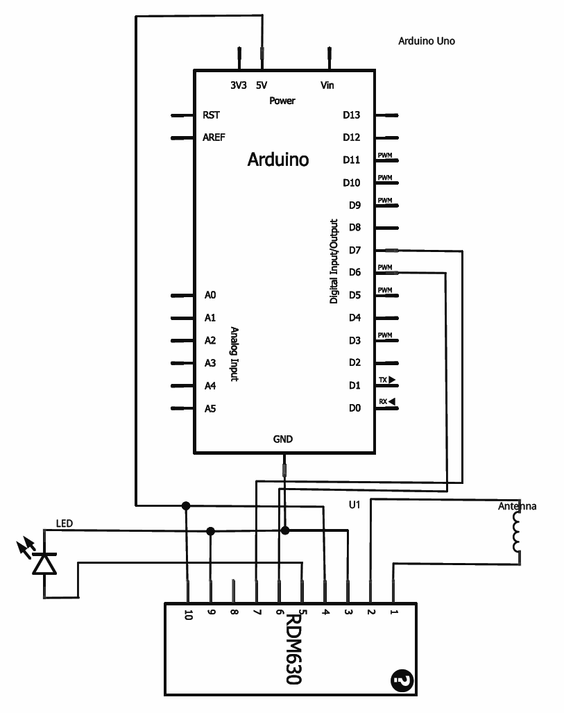
This tutorial provides guidance on integrating RFID functionality into a project using the RDM630 module from Seeed Studio, specifically its UART version. The module is mounted on a compact board with pre-soldered connectors, making it compatible with breadboards. To set...
breadboard How does current flow through this Arduino circuit
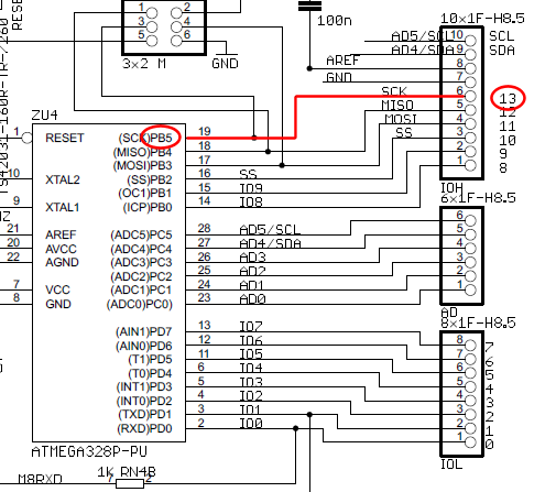
The wire connected to the 5V pin is linked to the positive pins of the breadboard, which are not connected to any other components. There are no additional connections on the positive column. While this may seem like a basic...
Make an Atom Synchronised Clock from a 1950s Slave Dial using Arduino
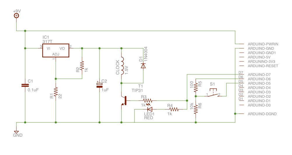
Upon purchasing the slave dial, it arrived without instructions, packaging, or additional details. The only visible markings, aside from decades of grime, were on the face (SMITH SECTRIC, ACELEC SYDNEY) and some markings on the bracket holding the mechanism (E....
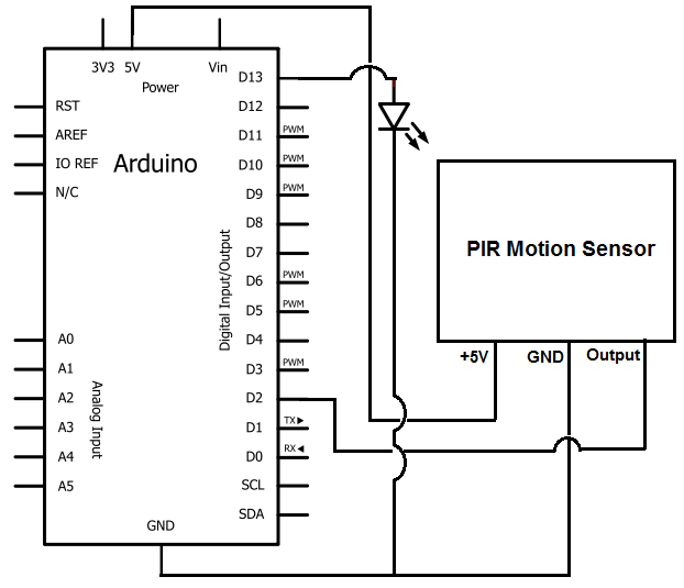
Arduino Motion Detector Circuit
Once the motion sensor detects motion, the Arduino can be programmed to activate an LED, turn on a motor, sound a buzzer, etc. In this circuit, for simplicity, an LED will be turned on when the motion sensor detects movement....
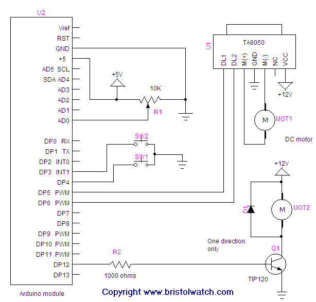
arduino pwm hb
Connecting and programming the TA8050 DC motor controller with the Arduino microcontroller.
The TA8050 is a versatile DC motor controller designed for use with microcontrollers, such as the Arduino. This controller allows for precise control of DC motors, making it suitable...
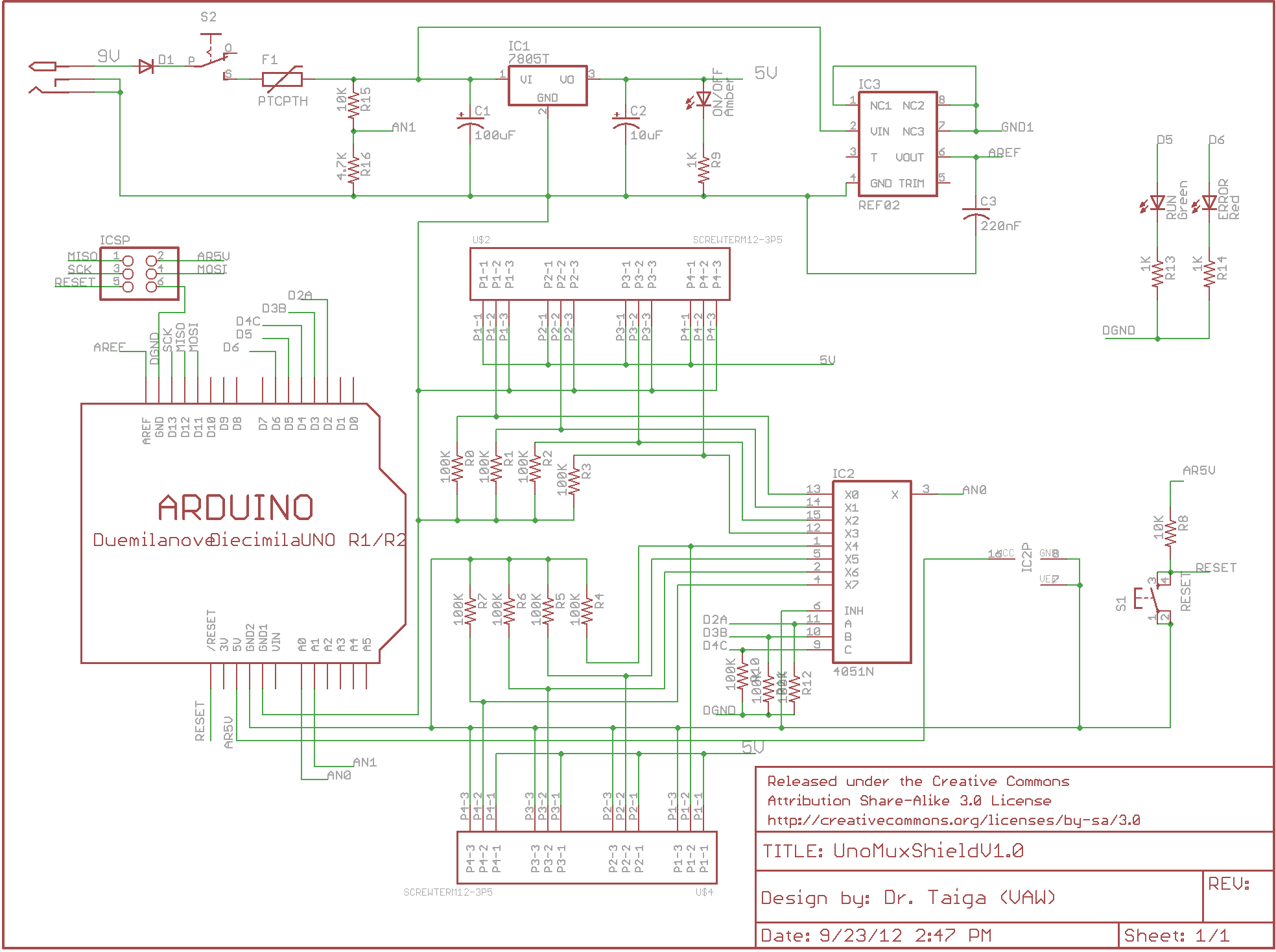
arduino multiplexer shield
There is enthusiasm for using Arduinos in science projects. However, it is important to address several shortcomings of the Arduino before it can be utilized for more serious applications. Specifically, the addition of robust screw terminals is necessary.
The Arduino platform...
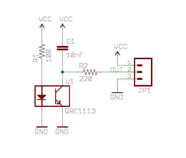
Honey Bee Counter Circuit
A real-time clock turns off the counter at night to conserve power. When a bee crosses under the LED, the light is reflected back to the sensor, which is a phototransistor, and triggers a digital input to the Arduino (or...
arduino pulse to transistor power maximum
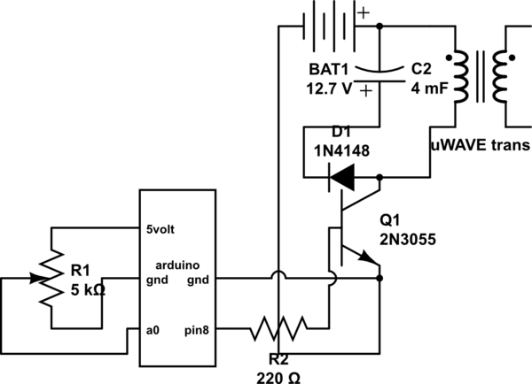
If both devices need to be powered from the battery, should the emitter be connected to the ground of the Arduino and the battery to prevent current from flowing through the Arduino ground, ensuring a clean pulse? Alternatively, can the...
Arduino AVR High-Voltage Serial Programmer
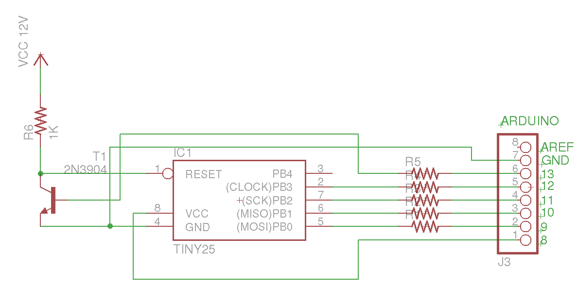
This Arduino sketch is designed to recover ATtiny microcontrollers that have become non-functional due to incorrect fuse settings. It achieves this by placing the affected ATtiny into high-voltage serial programming mode and rewriting the fuses to safe values. The Arduino...