


Air Handler Fan Wont Shut Off
#air handler
#fan control
#circuit board
#troubleshooting
#Goodman Janitrol
#HVAC
#electrical wiring
#capacitor
#relay
#breaker
Description: A Goodman Janitrol 2.5-ton Standard Air Handler, model #ARUF030-00A-1, was diagnosed with a malfunction where the fan could only be turned off by either switching off the breaker or disconnecting the black wire leading from the fan to the circuit board. The fan has five connected wires: two brown wires go to the capacitor, two wires (red and black) connect to the circuit board, and one purple wire connects to the contactor relay. Troubleshooting indicated that the issue lies with the black wire, as disconnecting it is the only method, aside from turning off the breaker, that stops the fan from running. When the black wire is connected and all other wires are disconnected, the fan continues to operate. Conversely, when the black wire is disconnected and all other wires are connected, the fan does not run. This situation raises the question of whether the circuit board needs replacement. The estimated cost of a new board ranges from $200 to $300, while installing a relay to control the fan via the thermostat would cost approximately $20. It is essential to ensure that the thermostat is set to 'fan auto' and to consider if the fan has been recently replaced. Continuous operation of the fan in air handlers often indicates a sequencer problem unless the Goodman model utilizes a sequencer style fan control instead of a circuit board. A digital thermometer can help measure heat rise across the air handler with the thermostat off, although professionals typically measure amperage.
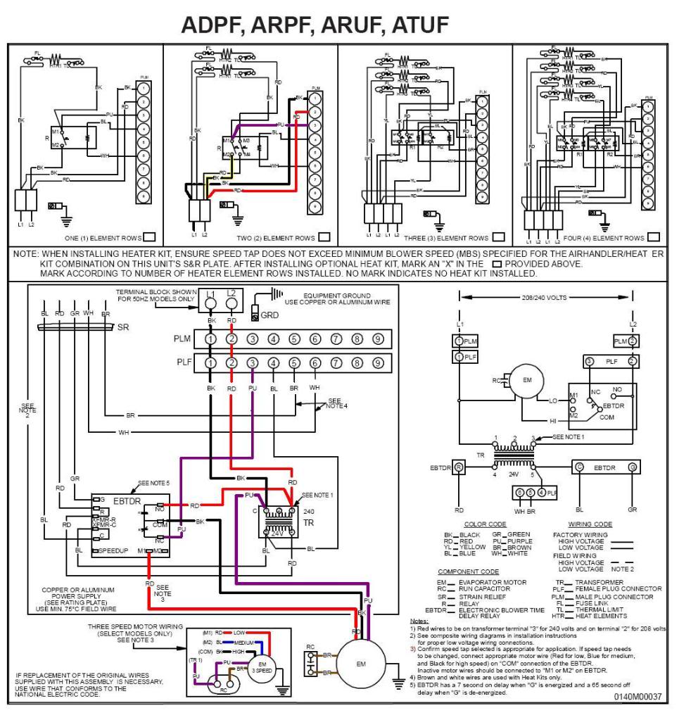
Further inquiry revealed that the contractor relay, referred to as the transformer, was disconnected in an attempt to troubleshoot the issue. Upon reconnecting the wires, uncertainty arose regarding their correct placement, particularly since the thermostat was not functioning after the reconnection. The transformer has five ports: the top left port connects to purple/black, the top middle is unoccupied, the top right has red/red, the bottom left has blue/blue, and the bottom right has a red wire. Verification of the wiring diagram confirmed correct reconnection, yet the thermostat remained non-functional. After disconnecting the purple wire from NC as recommended, the fan did not activate when the breaker was turned on, and attempts to adjust the thermostat yielded no results. Notably, the fan became hot even when turned off, leading to concerns about potential damage. The thermostat's operation was further complicated by an incident where the transformer was dropped, raising questions about possible internal damage affecting performance. The presence of a burnt smell after the purple wire was disconnected and the fan remained hot, despite being turned off, necessitates further investigation into the thermostat's functionality and the overall system integrity.A Goodman Janitrol 2. 5 ton Standard Air Handler model #ARUF030-00A-1. After troubleshooting, I discovered that the only way to shut the fan off is by turning off the breaker or disconnecting the black wire that leads from the fan to the circuit board. There are 5 wires connected to the fan. 2 (brown) go to the capacitor, 2 (red, black) to the circuit board and 1 (purple) to the contractor relay.
After extensive trouble shooting I narrowed the problem to be with the black wire that leads from the fan to the circuit board because disconnecting that wire is the only way besides shutting off the breaker that stops the fan from running. With the black wire connected and all the other wires disconnected the fan continues to run but with the black wire disconnected and all the other wires connected the fan does not run.
Am I correct with my assumption and if so does it mean that the whole board will have to be replaced Yeah, looks like you would have to replace the board. Or if you prefer, you could install a relay and make the fan go on and off with the thermostat. Boards usually cost 200 to 300 dollars, while a relay will cost you about 20 dollars. You are sure that the t stat is set to fan auto Did you recently replace the fan A fan continuously running on air handlers is usually a sequencer problem.
(Unless it is a Goodman with the sequencer style fan control instead of the circuit board) A digital "meat" thermometer can help determine if we have a heat rise across the air handler with the thermostat turned off. (Pros would usually measure amperage) Houston204, before I posted to this site, I disconnected the the contractor relay which I just learned is called the transformer because I thought it was the problem and I reconnected the wires but I am not sure if I reconnected correctly because now the thermostat won`t turn on at the wall location.
It was working just fine prior to me disconnecting the wires and taking the transformer into the store. Can you help me determine if the wires are correctly connected to the right port before I move on to the step that you recommended I take in your reply.
There are 5 ports on the transformer (3 top, 2 bottom) the top left port has purple/black, top middle is empty, top right has red/red, bottom left has blue/blue and the bottom right has a red wire. Houston204, using the diagram I was able to verify that I did reconnect the wires correctly. However, the stat still won ’t work. Although the stat has now become a problem I proceeded on to disconnect the purple wire from NC as you had recommended and when I turned the breaker back on the fan did not come on so I messed around with the thermostat controls but still nothing.
I turned the breaker back off and when I got back up to the attic the fan was really hot. I let the fan cool off then I reconnected the purple wire and turned the breaker back on and the fan did not come back on nor did it heat up (the thermostat was in the off position). Could this mean that the fan problem has been corrected and if so how do I proceed with figuring out what`s now happening with the thermostat Hoston204, I removed the red and black wire from the EBTDR to test the thermostat and I put them right back in the correct place.
I also disconnected the wires from the transformer to remove it, then I reconnected those wires back correctly. However, when I was on my way back up to the attic to reinstall the transformer I dropped it from the top of the ladder onto the hardwood floor.
Could that be the reason why the thermostat was working prior to me taking it off and now it doesn ’t Last night after removing the purple wire from NC as you recommended and turning the breaker on and off, when I went back up to the attic and noticed that the fan was hot even though it did not turn on, I smelled a brunt smell but I thought it was coming from the fan since the fan was hot but it may have been comin
Further inquiry revealed that the contractor relay, referred to as the transformer, was disconnected in an attempt to troubleshoot the issue. Upon reconnecting the wires, uncertainty arose regarding their correct placement, particularly since the thermostat was not functioning after the reconnection. The transformer has five ports: the top left port connects to purple/black, the top middle is unoccupied, the top right has red/red, the bottom left has blue/blue, and the bottom right has a red wire. Verification of the wiring diagram confirmed correct reconnection, yet the thermostat remained non-functional. After disconnecting the purple wire from NC as recommended, the fan did not activate when the breaker was turned on, and attempts to adjust the thermostat yielded no results. Notably, the fan became hot even when turned off, leading to concerns about potential damage. The thermostat's operation was further complicated by an incident where the transformer was dropped, raising questions about possible internal damage affecting performance. The presence of a burnt smell after the purple wire was disconnected and the fan remained hot, despite being turned off, necessitates further investigation into the thermostat's functionality and the overall system integrity.A Goodman Janitrol 2. 5 ton Standard Air Handler model #ARUF030-00A-1. After troubleshooting, I discovered that the only way to shut the fan off is by turning off the breaker or disconnecting the black wire that leads from the fan to the circuit board. There are 5 wires connected to the fan. 2 (brown) go to the capacitor, 2 (red, black) to the circuit board and 1 (purple) to the contractor relay.
After extensive trouble shooting I narrowed the problem to be with the black wire that leads from the fan to the circuit board because disconnecting that wire is the only way besides shutting off the breaker that stops the fan from running. With the black wire connected and all the other wires disconnected the fan continues to run but with the black wire disconnected and all the other wires connected the fan does not run.
Am I correct with my assumption and if so does it mean that the whole board will have to be replaced Yeah, looks like you would have to replace the board. Or if you prefer, you could install a relay and make the fan go on and off with the thermostat. Boards usually cost 200 to 300 dollars, while a relay will cost you about 20 dollars. You are sure that the t stat is set to fan auto Did you recently replace the fan A fan continuously running on air handlers is usually a sequencer problem.
(Unless it is a Goodman with the sequencer style fan control instead of the circuit board) A digital "meat" thermometer can help determine if we have a heat rise across the air handler with the thermostat turned off. (Pros would usually measure amperage) Houston204, before I posted to this site, I disconnected the the contractor relay which I just learned is called the transformer because I thought it was the problem and I reconnected the wires but I am not sure if I reconnected correctly because now the thermostat won`t turn on at the wall location.
It was working just fine prior to me disconnecting the wires and taking the transformer into the store. Can you help me determine if the wires are correctly connected to the right port before I move on to the step that you recommended I take in your reply.
There are 5 ports on the transformer (3 top, 2 bottom) the top left port has purple/black, top middle is empty, top right has red/red, bottom left has blue/blue and the bottom right has a red wire. Houston204, using the diagram I was able to verify that I did reconnect the wires correctly. However, the stat still won ’t work. Although the stat has now become a problem I proceeded on to disconnect the purple wire from NC as you had recommended and when I turned the breaker back on the fan did not come on so I messed around with the thermostat controls but still nothing.
I turned the breaker back off and when I got back up to the attic the fan was really hot. I let the fan cool off then I reconnected the purple wire and turned the breaker back on and the fan did not come back on nor did it heat up (the thermostat was in the off position). Could this mean that the fan problem has been corrected and if so how do I proceed with figuring out what`s now happening with the thermostat Hoston204, I removed the red and black wire from the EBTDR to test the thermostat and I put them right back in the correct place.
I also disconnected the wires from the transformer to remove it, then I reconnected those wires back correctly. However, when I was on my way back up to the attic to reinstall the transformer I dropped it from the top of the ladder onto the hardwood floor.
Could that be the reason why the thermostat was working prior to me taking it off and now it doesn ’t Last night after removing the purple wire from NC as you recommended and turning the breaker on and off, when I went back up to the attic and noticed that the fan was hot even though it did not turn on, I smelled a brunt smell but I thought it was coming from the fan since the fan was hot but it may have been comin
Dean Forest Railway Telecoms
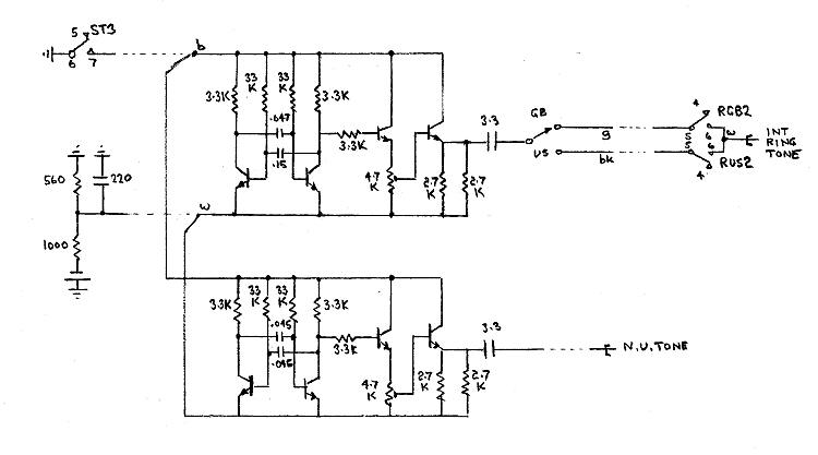
Each line key has three positions. In the centralized position, it connects the line circuit to the line to await a call. In the downward position (KK), it operates a K relay which switches the line through to the common...
Help me Understand this Circuit Schematic
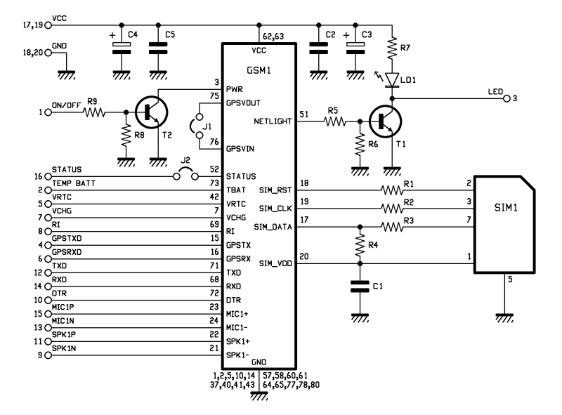
The roles of capacitors C1, C4, and C5 in a circuit may not be immediately clear. Capacitors on the power rail help to smooth out the signal by reducing current ripple, which can be observed using an oscilloscope. Resistors R6...
a more practical capacitor powered
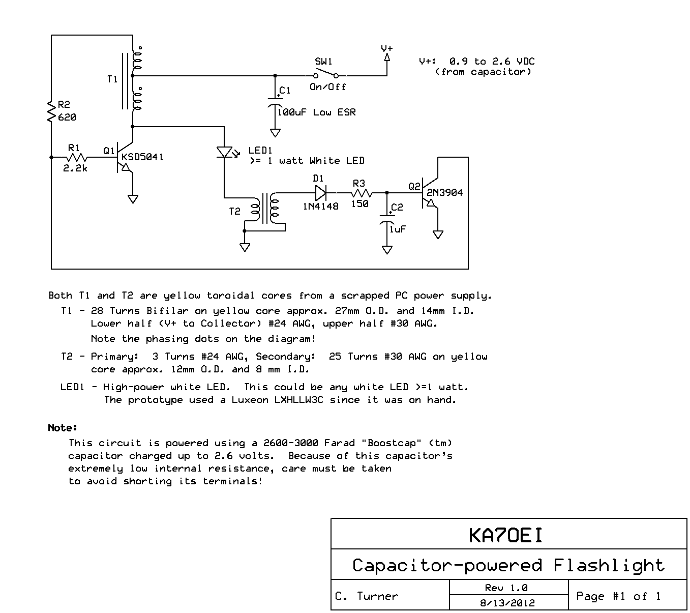
The inexpensive flashlight utilized a small (0.22 Farad) capacitor for energy storage, which provided approximately 6.6 Joules of energy, significantly less than 1/1000th of the energy contained in a single AA alkaline cell. As a standard "super capacitor," it had...
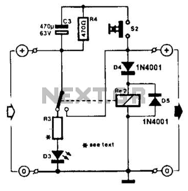
Relay Fuse For Battery Charges Circuit
A charged capacitor C3 and a momentary pushbutton switch S2 are utilized to temporarily activate relay RE2. The battery being charged powers the relay to maintain its closed state. Additionally, S2 can energize the relay even if the battery is...
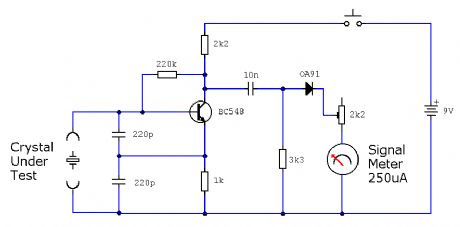
ELF MONITOR
The capacitor instrument is not intended for measuring the capacitance of capacitors; rather, it is designed to identify whether a capacitor is functional or defective, as well as to detect short circuits or open circuits. This functionality provides reliable quality...
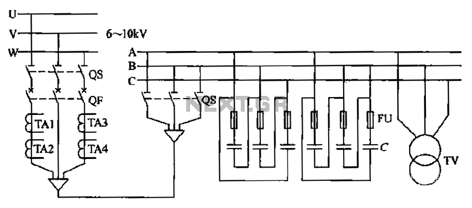
High-pressure centralized compensation capacitor circuit
The compensation system is designed to focus on a high-pressure, high-voltage capacitor bank installed in the substation 6-10 kV bus. Compensation can only be implemented in this manner for the 6-10 kV bus before the reactive power on the line,...
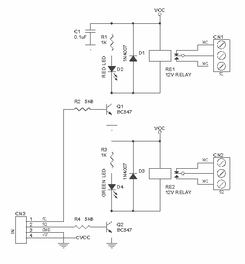
12V Relay Driver
Dual Channel Relay Board is a simple and convenient way to interface 2 relays for switching application in your project. Input - 12 VDC @ 84 mA. Output - two SPDT relay. Relay specification - 5 A @ 230 VAC....
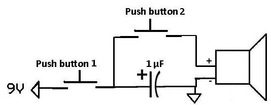
Apply a Pulse to a Speaker Using a Capacitor
This project demonstrates how a capacitor can supply a pulse signal to a speaker. A capacitor is charged and then discharges its voltage to a speaker, which acts as a transducer that converts electrical signals into sound. The result is...
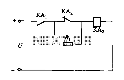
DC relay circuit to accelerate the release
A DC relay or contactor is utilized to enhance the excitation pull-in and release mechanisms in a circuit. The relay circuit, as depicted in Figure 6-28, facilitates improved return line efficiency. When the control relay KAi is activated, its normally...