


By the UCM-40-T and 74LS00 ultrasonic transmitter circuit consisting of NAND gate b
#555 timer
#ultrasonic transmitter
#NAND gate
#74LS00
#oscillator
#frequency adjustment
#potentiometer
#sensor
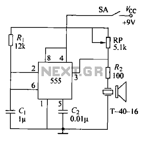
Description: The circuit comprises an ultrasonic transmitter and a T-4 0-16 555 timer circuit. By adjusting the potentiometer RP, the frequency of the oscillation circuit can be modified. The circuit emits ultrasonic signals at a frequency of 40 kHz, with an effective range of 3 feet from the output of the 555 timer. The circuit operates at a voltage of 9V and draws a current of 40 to 45 mA, with a control distance exceeding 8 meters.
The ultrasonic transmitter circuit utilizes a T-4 0-16 timer configured in astable mode to generate a square wave output at a frequency of 40 kHz. The 555 timer is a versatile integrated circuit widely used in timer, delay, pulse generation, and oscillator applications. In this configuration, the frequency of oscillation can be adjusted by varying the resistance of the potentiometer RP, which is part of the timing network along with a capacitor connected to the discharge pin of the 555 timer.
The output from the timer drives a transducer that converts the electrical signal into ultrasonic sound waves. The operating voltage of the circuit is set at 9V, which is supplied by a suitable power source. The current consumption of the circuit ranges from 40 mA to 45 mA, ensuring efficient operation while providing sufficient power to the ultrasonic transducer.
The effective control distance of the emitted ultrasonic signals is more than 8 meters, allowing for applications such as distance measurement, obstacle detection, or even in pest repellent systems. The design of the circuit is compact and can be easily integrated into various electronic projects requiring ultrasonic sensing capabilities. The choice of components, including the 555 timer and the ultrasonic transducer, ensures reliability and performance in the intended applications. Circuit consists of an ultrasonic transmitter and T-4 0-16 555 circuit, adjust the potentiometer RP can change the oscillation circuit frequency. 40k 3 feet from the output 555 of azelaic z} oscillating pulse-driven T-4 0-16 work, so that emit ultrasonic signals of 40kHz. Circuit operating voltage of 9V. Operating current 40 ~ 45mA, control distance is more than 8m.
The ultrasonic transmitter circuit utilizes a T-4 0-16 timer configured in astable mode to generate a square wave output at a frequency of 40 kHz. The 555 timer is a versatile integrated circuit widely used in timer, delay, pulse generation, and oscillator applications. In this configuration, the frequency of oscillation can be adjusted by varying the resistance of the potentiometer RP, which is part of the timing network along with a capacitor connected to the discharge pin of the 555 timer.
The output from the timer drives a transducer that converts the electrical signal into ultrasonic sound waves. The operating voltage of the circuit is set at 9V, which is supplied by a suitable power source. The current consumption of the circuit ranges from 40 mA to 45 mA, ensuring efficient operation while providing sufficient power to the ultrasonic transducer.
The effective control distance of the emitted ultrasonic signals is more than 8 meters, allowing for applications such as distance measurement, obstacle detection, or even in pest repellent systems. The design of the circuit is compact and can be easily integrated into various electronic projects requiring ultrasonic sensing capabilities. The choice of components, including the 555 timer and the ultrasonic transducer, ensures reliability and performance in the intended applications. Circuit consists of an ultrasonic transmitter and T-4 0-16 555 circuit, adjust the potentiometer RP can change the oscillation circuit frequency. 40k 3 feet from the output 555 of azelaic z} oscillating pulse-driven T-4 0-16 work, so that emit ultrasonic signals of 40kHz. Circuit operating voltage of 9V. Operating current 40 ~ 45mA, control distance is more than 8m.
555 Pulse Generator
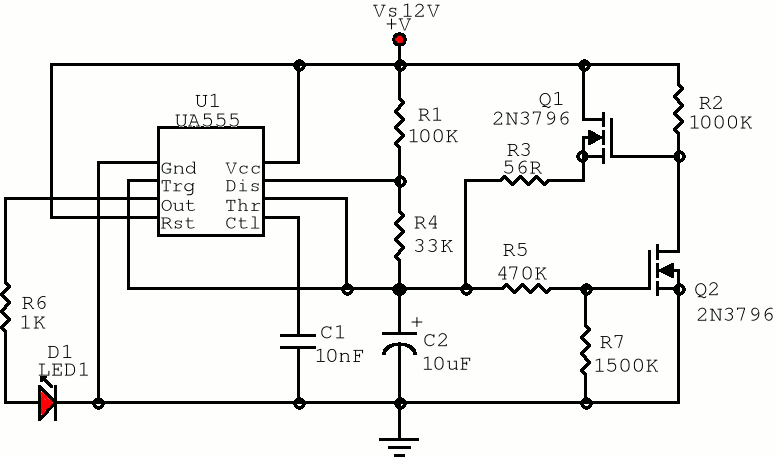
The first positive pulse from a classic 555-based oscillator is always 1.6 times longer than the subsequent pulses. This discrepancy arises because, during the initial cycle, capacitor C2 begins charging from 0 V. While this is typically not an issue,...
alternating flasher circuit diagram
This circuit utilizes three readily available 555 timer integrated circuits (ICs), all functioning as astable multivibrators. The first 555 timer has both an on period and an off period of 1 second. This IC regulates the on/off intervals of the...
Ammo Box Sequencer
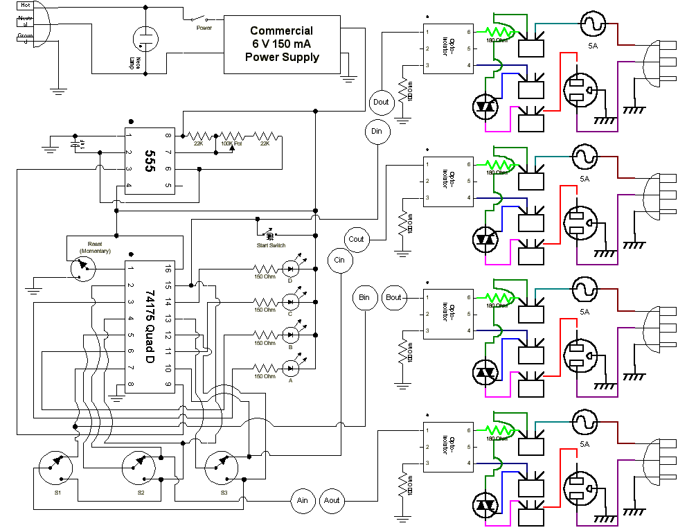
This is a sequencer circuit. Power to the logic portion of the circuit is provided by a standard commercial "wall-wart" power adapter supplying 6 VDC. The 555 timer IC generates the pulse train that drives the chase, with timing adjustable...
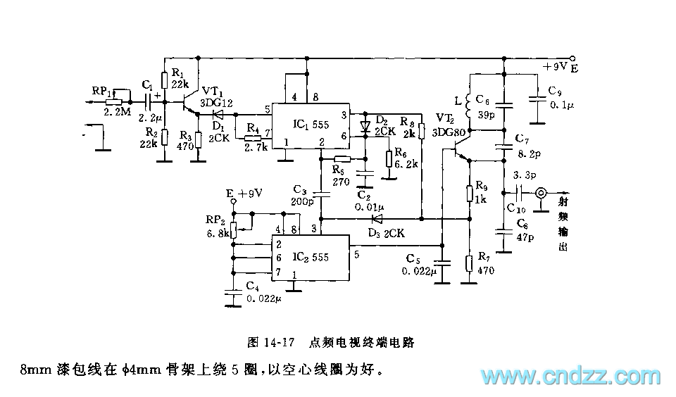
555 point-frequency TV terminal circuit
As shown in figure 14-17, this circuit consists of the input circuit, the line frequency synchronization generator, the sample-and-hold circuit, the voltage control delay generator, and the RF modulator. The input circuit includes the input attenuator RP1 and the emitter...
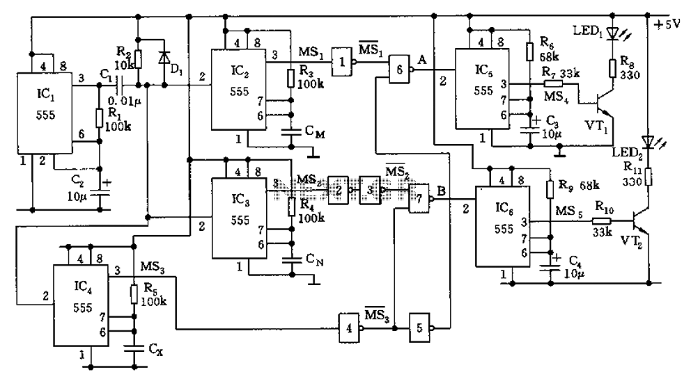
555 capacitor filter circuit diagrams
The capacitor filter operates by measuring the capacitance, which is proportional to the pulse width. This measurement is compared to a nominal capacitance to determine qualification. The circuit, as illustrated in the accompanying figure, includes IC1 along with resistors R1...
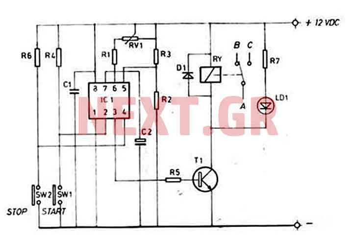
0-60sec start-stop timer with 555
This timer is ideal for small applications. Due to its simple structure, its usage and nevertheless its universal character, this mini timer is usable in the most current applications needing time intervals, from some seconds through approximately 60 minutes. By...
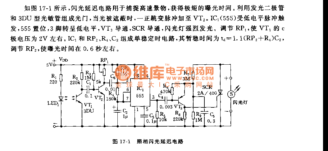
555 camera flash delay circuit
As shown in figure 17-1, the camera flash delay circuit is designed to capture high-speed scenes, allowing for very short exposure times. The light gate consists of a luminous diode and a 3DU type photosensitive tube. When the light is...
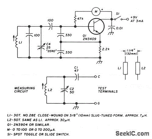
LC CHECKER
The circuit operates on the principle of the grid-dip or absorption effect, which takes place when a parallel resonant circuit is coupled to an oscillator operating at the same frequency. Transistor Q1 functions within a standard Colpitts oscillator circuit, maintaining...
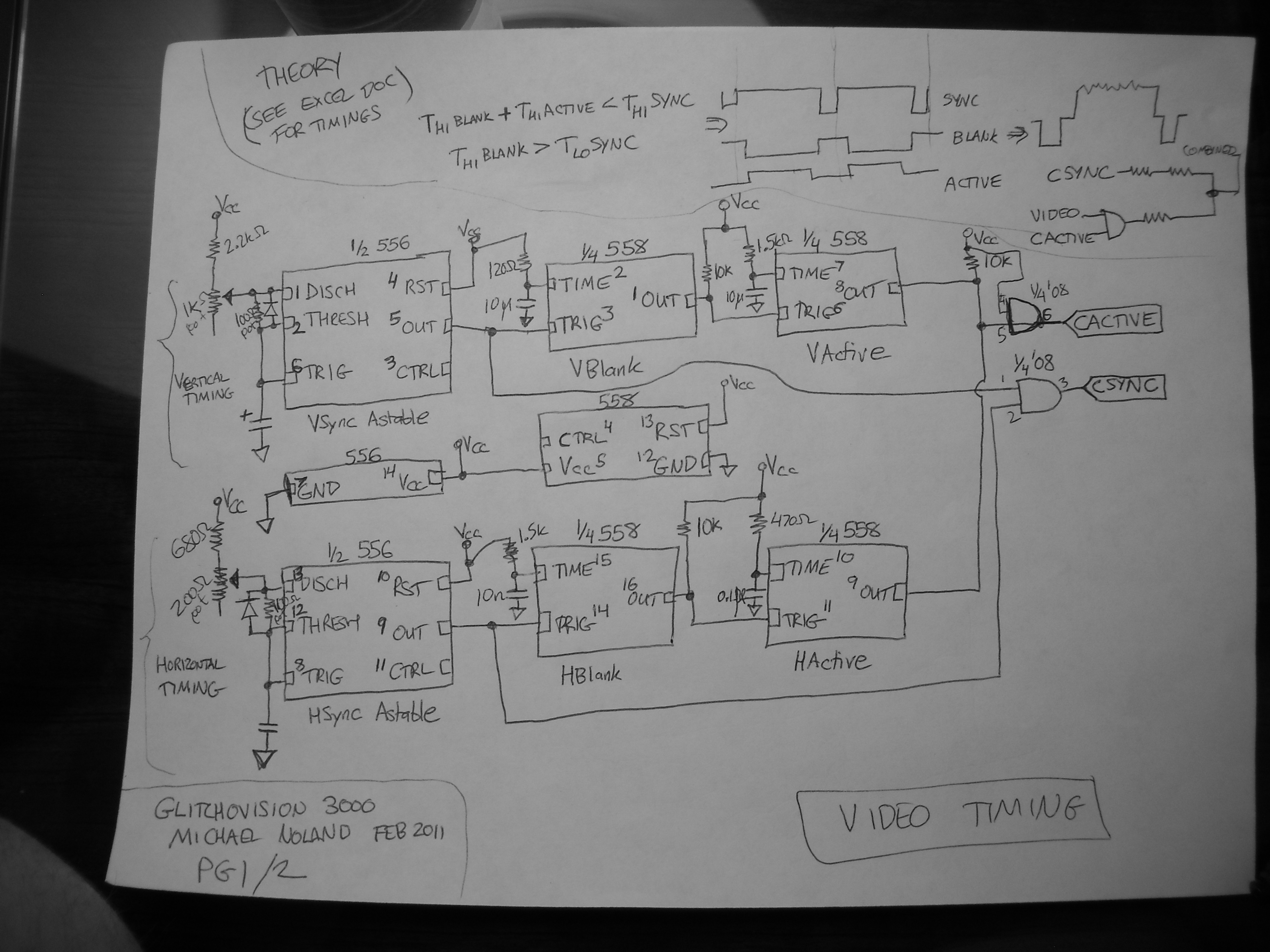
555 timer compo entry 2
This entry describes a four-step sequencer that controls an Atari Punk synth, accompanied by a grayscale NTSC video visualization of the output audio. The system is constructed using two 558 quad-timers and two 556 dual-timers. The video quality may not...