


C64DTV Color Fix
#video-mixer
#C64DTV
#moire
#buffer stage
#ASIC
#supply voltage
#schematic
#noise reduction
#electronics fix
#retro computing
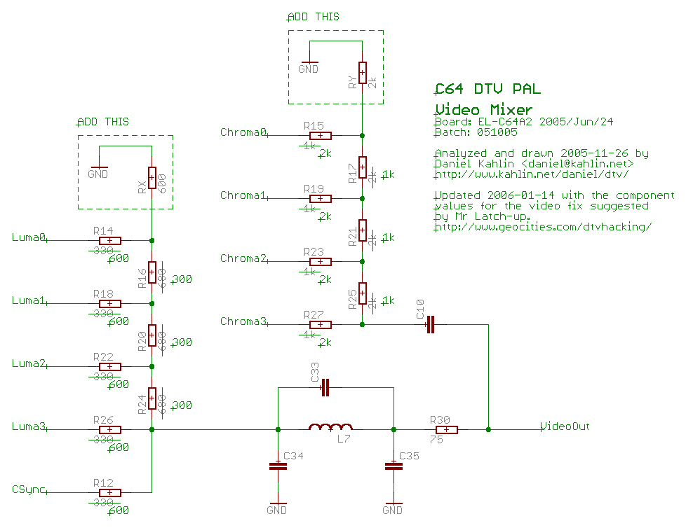
Description: The video mixer no longer requires a supply voltage, which could introduce moiré problems if the voltage is too noisy. As indicated in the schematic, the video mixer does not include an open-emitter buffer stage for any of the signals, unlike the original reference schematic that does include this buffer. The output of the C64DTV ASIC is not capable of handling that type of load smoothly. Due to the construction of the resistor ladder, the load is significantly higher on the more significant bits, which may result in the uneven steps observed. The amplitude of the Luma signal is low because the resistor ladder has a high impedance. Lowering the resistances in the Luma DAC is not feasible, as the C64DTV ASIC output cannot deliver the required load. On November 27, 2005, Nicolas Welte tested setting R14, R18, R22, and R26 to 680 ohms, and R16, R20, and R24 to 330 ohms. He added a crucial fix by connecting a 680-ohm resistor from the junction of R14/R16 to ground, which allowed access to the full range of colors, although the output appeared somewhat dark. It is suggested that changing R12 to 680 ohms may positively affect output brightness. The DTV manual states: "Drives high during non-sync times to set black level." On November 29, 2005, Michael BGhmer tested the complete fix with favorable results, but he was unable to test it with the 256-color test program due to limited access to his DTV.
The circuit described involves a video mixer that has been modified to eliminate the need for a supply voltage, which is advantageous in preventing potential moiré artifacts caused by noisy power supply lines. The absence of an open-emitter buffer stage in the current schematic is a notable departure from the original design, and this change significantly affects signal handling. The C64DTV ASIC output is sensitive to load variations, particularly in the context of the resistor ladder configuration.
The resistor ladder's design leads to a higher load on the more significant bits, which can cause uneven signal steps, impacting the overall color fidelity and signal quality. The impedance of the resistor ladder is a critical factor, especially for the Luma signal, which is characterized by a lower amplitude. The constraints imposed by the C64DTV ASIC's output capabilities necessitate careful selection of resistor values to ensure adequate signal strength without overloading the ASIC.
The adjustments made by Nicolas Welte, particularly the resistor values of R14, R18, R22, and R26 set to 680 ohms, and R16, R20, and R24 to 330 ohms, serve to balance the load across the resistor ladder and improve color output. The additional fix involving a 680-ohm resistor connected to ground from the junction of R14 and R16 is a crucial enhancement that allows for a more comprehensive color range, although it may lead to a darker output. The suggestion to modify R12 to 680 ohms is aimed at improving brightness levels, aligning with the DTV manual's guidance on setting black levels during non-sync times.
Overall, this circuit modification illustrates the intricate balance required in video signal processing, where component values must be meticulously adjusted to optimize performance and maintain signal integrity. The testing conducted by Michael BGhmer, although limited, indicates that these modifications yield positive results in practical applications, underscoring the importance of iterative testing and refinement in electronic circuit design.The video-mixer no longer requires a supply voltage. This supply voltage could introduce moire problems if too noisy. As seen in my schematic above the video-mixer does not have an open-emitter buffer stage for any of the signals. (the original reference schematic has this buffer) The output of the C64DTV ASIC does not handle that kind of load smoothly.
Due to how the resistor ladder is constructed, the load is much higher on the more significant bits. This could result in the uneven steps we see. The amplitude of the Luma signal is low because the resistor ladder has too high impedance. It wouldn`t be possible to lower the resistances in the Luma DAC, because the output of the C64DTV ASIC couldn`t deliver the load.
2005-11-27: Nicolas Welte tested setting R14, R18, R22, R26 to 680ohms, and R16, R20, R24 to 330ohms, but then added a crucial fix: 680ohms connected from the point between R14/R16 and ground. The full range of colors are then available. Although a little bit too dark. my comments: I think the output brightness might be affected in a good way if R12 is changed to 680ohms aswell.
In the DTV-Manual it says: "Drives high during non sync times to set black level. " 2005-11-29: Michael BG¶hmer tried the full fix simulated below with good results. Unfortunately Michael hasn`t been able to test with the 256 color test program. (he only had his DTV for 2 days, so no IEC connector yet)
The circuit described involves a video mixer that has been modified to eliminate the need for a supply voltage, which is advantageous in preventing potential moiré artifacts caused by noisy power supply lines. The absence of an open-emitter buffer stage in the current schematic is a notable departure from the original design, and this change significantly affects signal handling. The C64DTV ASIC output is sensitive to load variations, particularly in the context of the resistor ladder configuration.
The resistor ladder's design leads to a higher load on the more significant bits, which can cause uneven signal steps, impacting the overall color fidelity and signal quality. The impedance of the resistor ladder is a critical factor, especially for the Luma signal, which is characterized by a lower amplitude. The constraints imposed by the C64DTV ASIC's output capabilities necessitate careful selection of resistor values to ensure adequate signal strength without overloading the ASIC.
The adjustments made by Nicolas Welte, particularly the resistor values of R14, R18, R22, and R26 set to 680 ohms, and R16, R20, and R24 to 330 ohms, serve to balance the load across the resistor ladder and improve color output. The additional fix involving a 680-ohm resistor connected to ground from the junction of R14 and R16 is a crucial enhancement that allows for a more comprehensive color range, although it may lead to a darker output. The suggestion to modify R12 to 680 ohms is aimed at improving brightness levels, aligning with the DTV manual's guidance on setting black levels during non-sync times.
Overall, this circuit modification illustrates the intricate balance required in video signal processing, where component values must be meticulously adjusted to optimize performance and maintain signal integrity. The testing conducted by Michael BGhmer, although limited, indicates that these modifications yield positive results in practical applications, underscoring the importance of iterative testing and refinement in electronic circuit design.The video-mixer no longer requires a supply voltage. This supply voltage could introduce moire problems if too noisy. As seen in my schematic above the video-mixer does not have an open-emitter buffer stage for any of the signals. (the original reference schematic has this buffer) The output of the C64DTV ASIC does not handle that kind of load smoothly.
Due to how the resistor ladder is constructed, the load is much higher on the more significant bits. This could result in the uneven steps we see. The amplitude of the Luma signal is low because the resistor ladder has too high impedance. It wouldn`t be possible to lower the resistances in the Luma DAC, because the output of the C64DTV ASIC couldn`t deliver the load.
2005-11-27: Nicolas Welte tested setting R14, R18, R22, R26 to 680ohms, and R16, R20, R24 to 330ohms, but then added a crucial fix: 680ohms connected from the point between R14/R16 and ground. The full range of colors are then available. Although a little bit too dark. my comments: I think the output brightness might be affected in a good way if R12 is changed to 680ohms aswell.
In the DTV-Manual it says: "Drives high during non sync times to set black level. " 2005-11-29: Michael BG¶hmer tried the full fix simulated below with good results. Unfortunately Michael hasn`t been able to test with the 256 color test program. (he only had his DTV for 2 days, so no IEC connector yet)
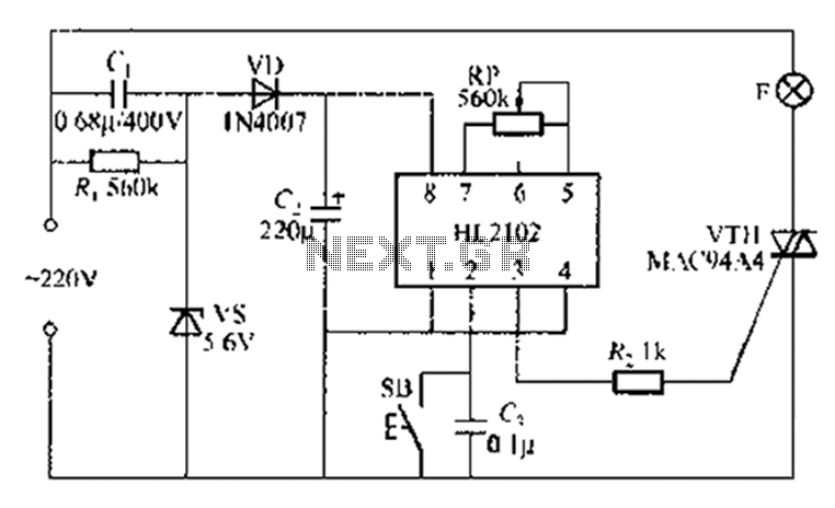
By ASIC delay lamp circuit
A thirty mining lamp control ASIC production delay lamp circuit is straightforward. It utilizes the HL2102 IC from Wuxi Love Core Microelectronics Co., Ltd. The circuit is designed to control a light with a timed delay, allowing for regular intervals...
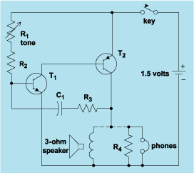
schematic diagram graphic arts
Schematic diagram. A presentation of the element-by-element relationship of all parts of a system.
A schematic diagram serves as a crucial tool in electronic design and engineering, representing the interconnections and relationships between various components within a system. It provides a...
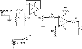
How to Read a Schematic
Electronic circuits are presented in schematic form. A schematic is essentially a map that illustrates the path of current through various components. Each component is represented by a symbol, typically accompanied by a label or a value, or both. The...
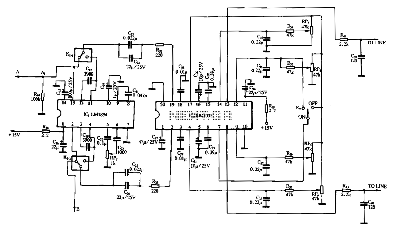
Dynamic noise reduction with DC volume control
A dynamic noise reduction circuit and a DC volume and tone balance control circuit, which are applied to the input stage and the discharge line between the amplifier.
The described circuit configuration incorporates two primary functions: dynamic noise reduction and volume/tone...
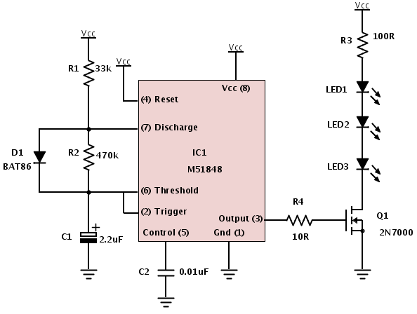
Building a device from a schematic
A common issue encountered is that individuals possess a schematic, also known as a circuit diagram, that they wish to construct. However, they discover that there are...
Building a circuit from a schematic requires a clear understanding of the components involved...
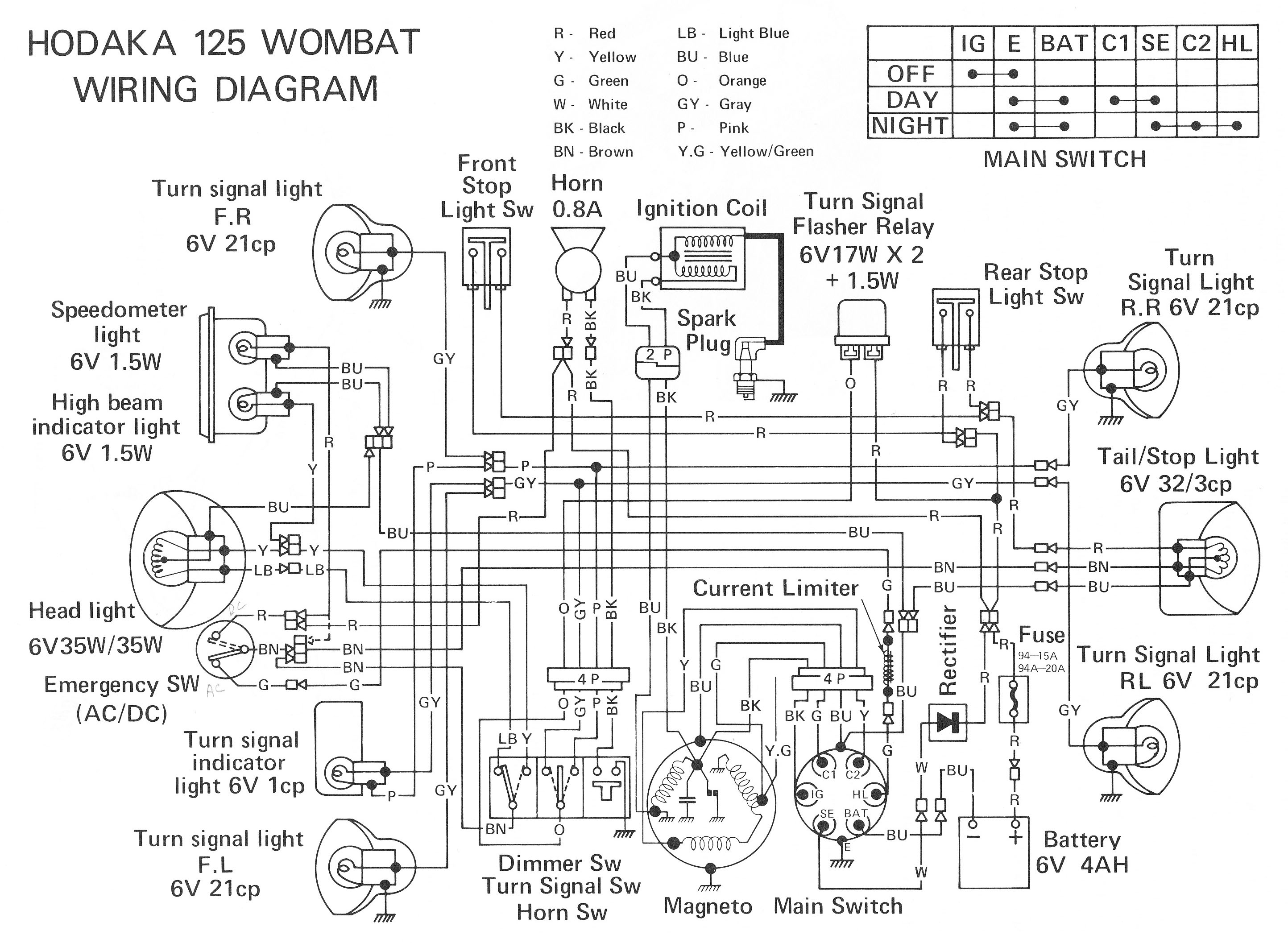
ELECTRONIC SCHEMATIC CIRCUIT DIAGRAMS
Electronic Schematic Circuit Diagrams Manual PDF Download.
The document provides a comprehensive manual that focuses on electronic schematic circuit diagrams. These diagrams are essential tools for understanding and designing electronic circuits, offering visual representations of circuit components and their interconnections. The...
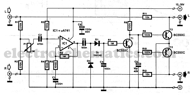
Stereo Noise Reduction Circuit
The noise reduction circuit is designed to minimize disturbances that occur during pauses in music playback. It functions by attenuating the signal output during these intervals.
The noise reduction circuit operates on the principle of detecting silence or low audio signals,...
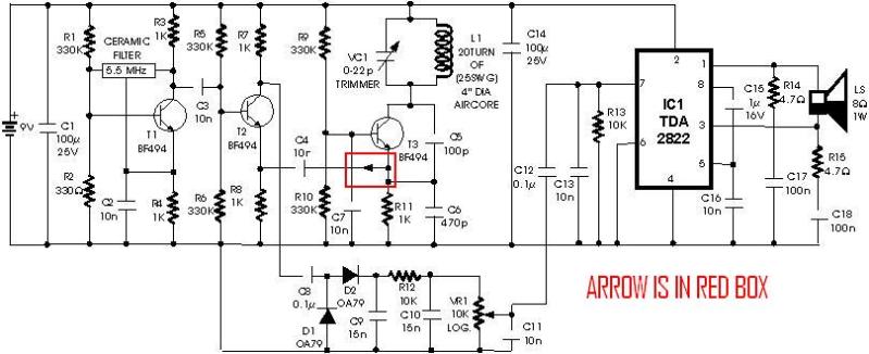
metal detector project circuit
A schematic diagram for a metal detector has been found. The project does not need to be original and can be sourced from the internet. There are several questions regarding this schematic. One query pertains to a small arrow connected...
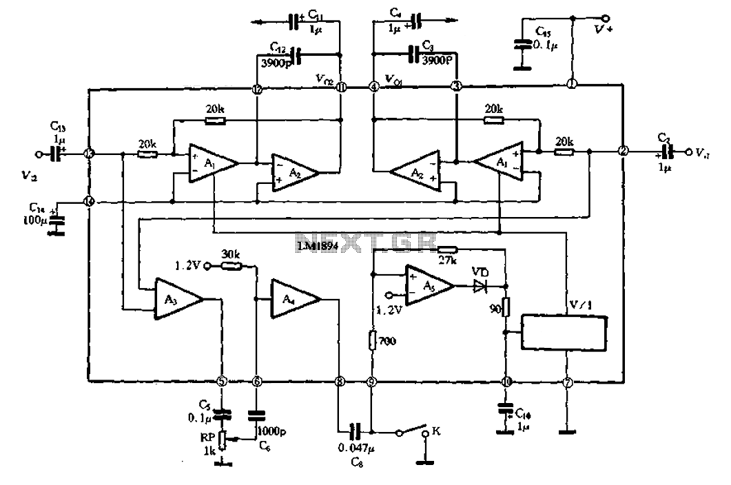
LM1894 Principles and Applications a
A typical representative of dynamic noise reduction developed by the United States National Semiconductor is the LM1894. Its principle is illustrated in Figure 1-1070, where the left and right input signals are processed through a main signal path. The input...