


Centrifugal fish autofeeder
#autofeeder
#fish feeder
#timer
#pellet dispenser
#home automation
#DIY
#pet care
#interval control
#low cost
#easy build
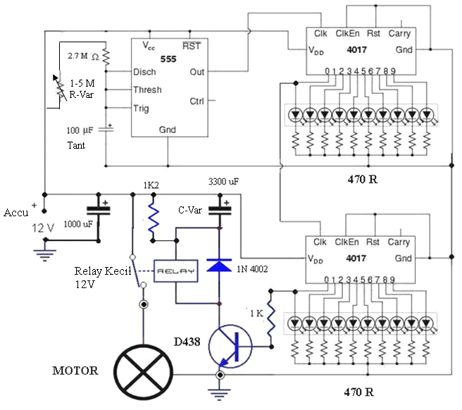
Description: This simple and cost-effective device is designed to automatically feed fish, alleviating concerns about their starvation. The autofeeder dispenses pellets based on user-defined quantities and time intervals. Constructing this circuit is an engaging activity that fosters creativity. The primary function of this device is to serve as a timer with progress indication, utilizing the interaction between a relay and a capacitor to control the amount of pellets dispensed. The circuit employs a standard timer (IC 555) that generates pulses sent to two cascaded CMOS 4017 counters. The output from the last counter is connected in series with a capacitor and relay. It is important to note that a relay possesses its own resistance, which influences the timing of the operation. When activated, the relay operates for a specific duration, allowing the motor to expel pellets through centrifugal force. The capacitor charges until it reaches full capacity, at which point the relay deactivates. Consequently, the larger the capacitor, the longer the relay remains engaged, resulting in extended motor operation for pellet dispensing. A resistor is included to discharge the capacitor, preparing it for the next cycle. For example, if the timer is set to T = 3 minutes, the counters multiply the time to 10 x 10 = 100, leading to a total interval of T = 3 minutes x 100 = 300 minutes, or 5 hours. Adjusting the time intervals can be accomplished by modifying the variable resistor (R-Var), while the pellet quantity can be altered by changing the capacitor size (C-Var). Required components for assembly include a 12V tape motor, a ring (plastic or brass), transmission cable, two plastic bottles, adhesive for securing the motor, a coin (approximately matching the bottle neck diameter), a cutter, matches, and soldering tools. The project encourages hands-on construction, guided by provided images.
The circuit operates on a principle of timed intervals and controlled output, making it suitable for users who wish to automate fish feeding. The integration of the IC 555 timer is crucial as it generates precise timing pulses that dictate the operation of the CMOS 4017 counters. Each counter in the series serves to extend the timing capability, enabling the user to set longer feeding intervals. The relay acts as a switch that controls the motor operation, allowing it to run for a predetermined duration based on the charge of the capacitor.
The design also emphasizes the importance of component selection, particularly the capacitor, which directly influences the feeding duration. Users can experiment with different capacitor values to achieve the desired output. Additionally, the use of a resistor to discharge the capacitor ensures that the system resets properly for the next feeding cycle.
Overall, this autofeeder circuit not only provides a practical solution for fish care but also serves as an educational project that enhances understanding of timer circuits, relay operation, and the principles of automation in electronic devices. The assembly process encourages creativity and problem-solving, making it an excellent project for hobbyists and electronics enthusiasts.This easy as well as cheap but effective device is mainly intended for your ease to leave your fish autofed. You need no longer worry your fish would starve as this autofeeder would replace your job. This autofeeder device will expell pellets by quantity as well as time intervals as you like. Besides, making this circuit seems to be a bit entertai ning as you are insisted to make it yourself and so It would develop your creativity. Don`t worry, it works! The main role of this section functions as a timer (few hour intervals) with progress indicator and the mutual action of the relay and capasitor functioning as expelled quantity of pellets. The circuit is using regular timer (IC 555) sending pulse to 2 cascaded counters of CMOS 4017. The output pin from the last counter is then fed to the capacitor and-relay in series. (Remember: a relay owns its own resistance) which consequently trigger the relay for some time to turn on mechanics section.
After the capacitor is about to be fully loaded, the relay shuts off. From here we could figure out that the bigger the capacity the longer the relay connects which then causes the motor works to expel pellets centrifugally. The resistor functions to unload the capacitor so that the capacitor is then ready to be loaded for the next cycle.
For short, if we set the timer T = 3 minutes, the both counters will multiply the time to be 10 x 10 = 100 times. So the total time intervals would be T = 3 minutes x 10 x 10 = 300 minutes = 5 hours. To change the time intervals simply is by changes/turning R-Var and for the pellet quantity is by changing C-Var size.
All you need for this section are tape motor 12 V + the ring (plastic or brass), transmission cable, 2 plastic bottle (as shown on the pic), some glue to stick the motor, a coin (about to reach the bottle neck diameter, cutter, match, and solder. For short, try making it yourself following these pics (try to develop yourself about my brief idea):
The circuit operates on a principle of timed intervals and controlled output, making it suitable for users who wish to automate fish feeding. The integration of the IC 555 timer is crucial as it generates precise timing pulses that dictate the operation of the CMOS 4017 counters. Each counter in the series serves to extend the timing capability, enabling the user to set longer feeding intervals. The relay acts as a switch that controls the motor operation, allowing it to run for a predetermined duration based on the charge of the capacitor.
The design also emphasizes the importance of component selection, particularly the capacitor, which directly influences the feeding duration. Users can experiment with different capacitor values to achieve the desired output. Additionally, the use of a resistor to discharge the capacitor ensures that the system resets properly for the next feeding cycle.
Overall, this autofeeder circuit not only provides a practical solution for fish care but also serves as an educational project that enhances understanding of timer circuits, relay operation, and the principles of automation in electronic devices. The assembly process encourages creativity and problem-solving, making it an excellent project for hobbyists and electronics enthusiasts.This easy as well as cheap but effective device is mainly intended for your ease to leave your fish autofed. You need no longer worry your fish would starve as this autofeeder would replace your job. This autofeeder device will expell pellets by quantity as well as time intervals as you like. Besides, making this circuit seems to be a bit entertai ning as you are insisted to make it yourself and so It would develop your creativity. Don`t worry, it works! The main role of this section functions as a timer (few hour intervals) with progress indicator and the mutual action of the relay and capasitor functioning as expelled quantity of pellets. The circuit is using regular timer (IC 555) sending pulse to 2 cascaded counters of CMOS 4017. The output pin from the last counter is then fed to the capacitor and-relay in series. (Remember: a relay owns its own resistance) which consequently trigger the relay for some time to turn on mechanics section.
After the capacitor is about to be fully loaded, the relay shuts off. From here we could figure out that the bigger the capacity the longer the relay connects which then causes the motor works to expel pellets centrifugally. The resistor functions to unload the capacitor so that the capacitor is then ready to be loaded for the next cycle.
For short, if we set the timer T = 3 minutes, the both counters will multiply the time to be 10 x 10 = 100 times. So the total time intervals would be T = 3 minutes x 10 x 10 = 300 minutes = 5 hours. To change the time intervals simply is by changes/turning R-Var and for the pellet quantity is by changing C-Var size.
All you need for this section are tape motor 12 V + the ring (plastic or brass), transmission cable, 2 plastic bottle (as shown on the pic), some glue to stick the motor, a coin (about to reach the bottle neck diameter, cutter, match, and solder. For short, try making it yourself following these pics (try to develop yourself about my brief idea):
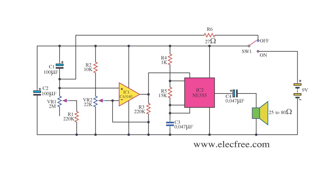
Simple Timer by CA3140 + NE555
This circuit sets the time using a simple model that can accurately maintain the time over extended periods. It employs the CA3140 integrated circuit for its functionality.
The circuit utilizes the CA3140 operational amplifier, which is known for its high precision...
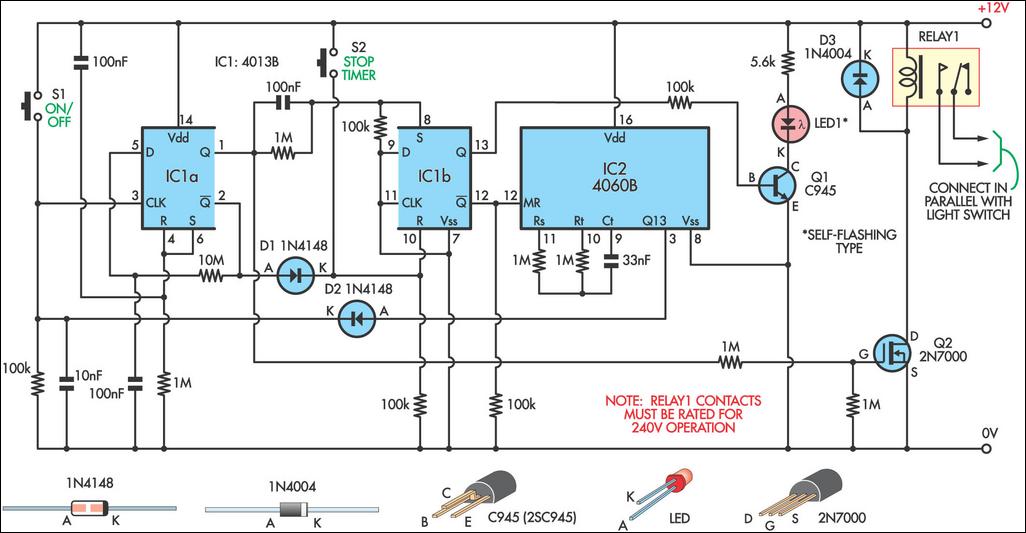
Switch Timer For Bathroom Light
This 9-minute timer switch can be utilized to control lighting in a toilet or bathroom. The timer is activated by pressing switch S1 and deactivated by pressing S1 again. If the timer is not manually turned off, the light will...
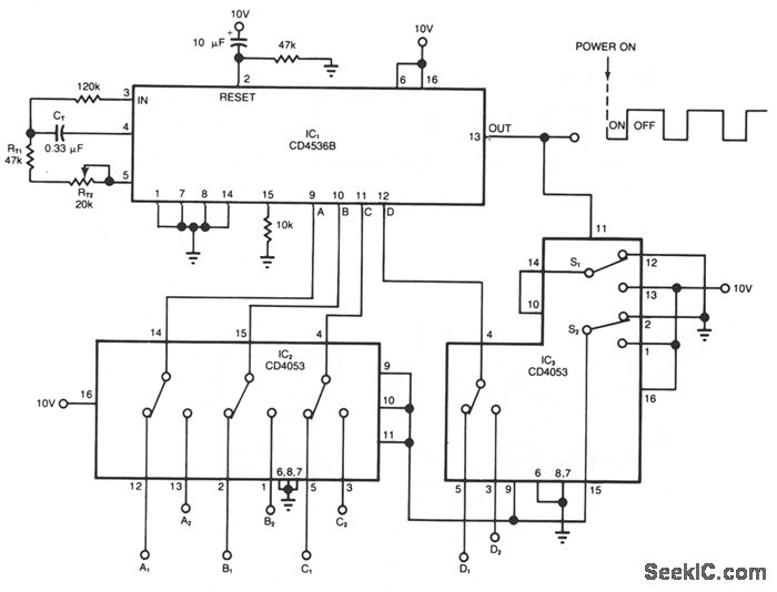
SEQUENTIAL TIMER
The timer circuit provides independent control of the output's on and off intervals, which can range from 0.055 seconds to 30 minutes, with minimal impact from power-line transients. IC1 is a CMOS programmable timer chip that features 24 ripple-binary counter...
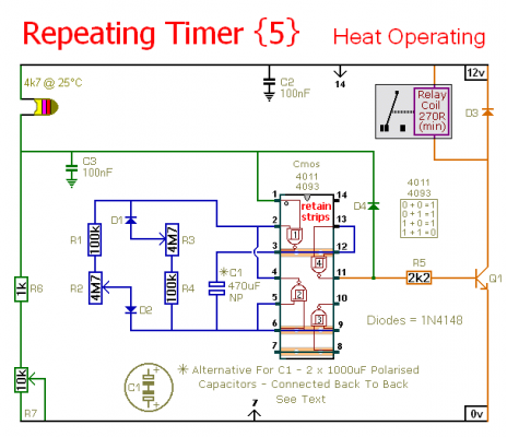
Repeating Timer No5
This circuit is a temperature-controlled version of Repeating Timer No. 3. The light-dependent resistor has been replaced by a temperature-dependent resistor, or thermistor. A small preset potentiometer allows the user to select the temperature threshold above which the timer will...

Low Cost Universal Battery Charger Schematic
This is a simple and low-cost NiCd and NiMH battery charger. The schematic diagram indicates that the charging current (I) should be set to 1/10 of the battery's rated capacity. For instance, if the battery has a rated capacity of...
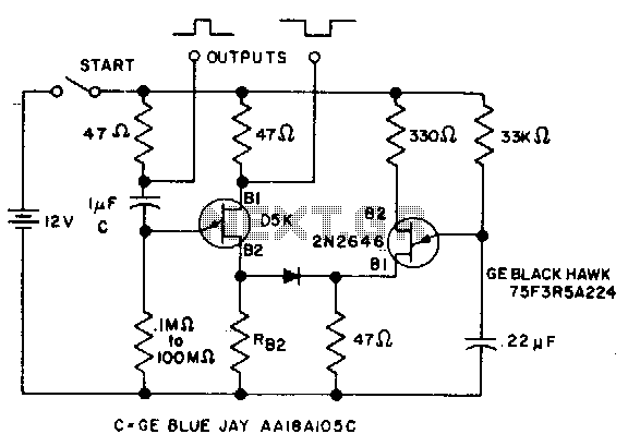
0.1 To 90 second timer
The timer interval begins when power is supplied to the circuit and ends when voltage is applied to the load. The 2N2646 transistor is utilized in the oscillator, which generates pulses to the base of the D5K. This configuration decreases...
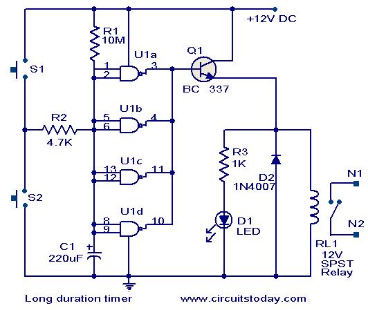
Long duration timer circuit
This timer circuit is designed to turn off a specific device after approximately 35 minutes. It can be utilized to switch off appliances such as radios, TVs, fans, and pumps after a predetermined duration of 35 minutes, contributing to significant...
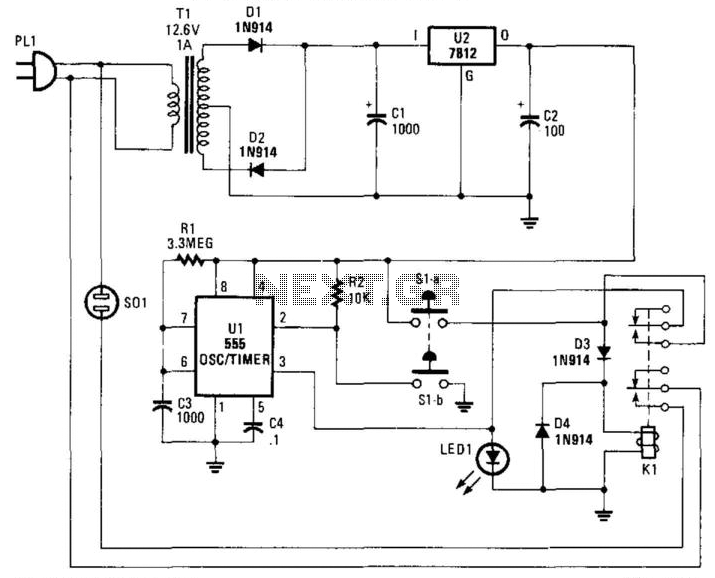
Appliance Cutoff Timer
Suitable for cutting off an appliance or other AC load, this timer will cut the AC power after a period determined by R1/C3, as shown, for about 40 minutes. K1 is a relay that should handle about 10 A. S1A...
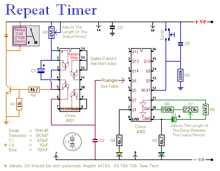
Repeating Interval Timer circuit
This circuit features an adjustable output timer capable of re-triggering at specified intervals. The output duration can range from a fraction of a second to over half an hour, with the ability to recur at regular intervals spanning from seconds...