


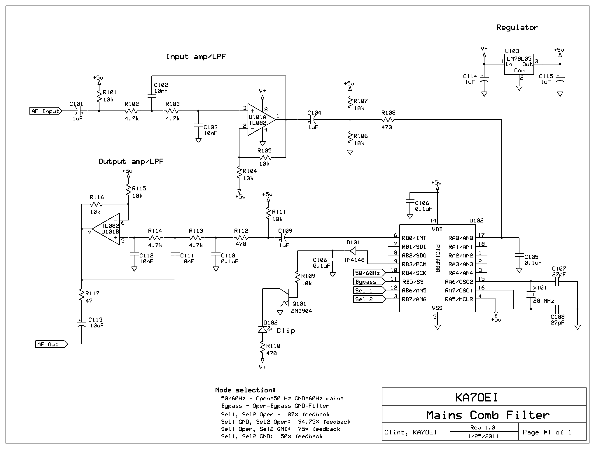
comb filter
#optical filter
#light reduction
#LED
#narrowband filter
#receiver
#spectral width
#simple optical system
#off-wavelength rejection
Description: The use of optical filters to reduce or eliminate light from other sources is discussed. A narrowband optical filter on the receiver can reject "off-wavelength" light; however, these filters tend to be expensive and challenging to implement in simple optical systems. Additionally, some filters may not be compatible with the wide spectral width of LED-based emitters. An alternative approach involves using theatrical "gels" selected to pass the desired wavelength with minimal attenuation while blocking certain dominant wavelengths of light pollution. For red LEDs (615-650 nanometers), the Roscolux "Fire" (#19) theatrical gel filter has been shown to reduce the impact of high-pressure sodium and mercury vapor light pollution by approximately 6 dB while minimally affecting the desired signals.
To narrow the beamwidth, a large-aperture lens coupled with a small-area photodetector can reduce the field of view of the detector, allowing for better discrimination against off-axis interfering sources. This can be achieved with a photodetector that has an active area similar in size to the "blur circle" of the lens system or by masking a larger detector to a size slightly larger than the lens system's blur circle. Slightly off-pointing the receiver can further enhance the rejection of noise sources. Even if the desired signal is reduced, the overall improvement in the signal-to-noise ratio can occur if the interfering light source is positioned farther off-point than the desired signal.
Another method involves using a subcarrier on the link instead of baseband transmission. This technique shifts the audio frequency to a range above where most mains-induced interference occurs, provided the receiver is not overloaded by light. However, using higher frequencies can decrease the effective sensitivity of the receiver, as many sensitive detectors exhibit reduced performance at increased frequencies. If there is sufficient excess link margin, this method may still be effective. The need for additional equipment for the generation and demodulation of the subcarrier complicates the overall setup.
An averaged spectral plot of an audio file recorded during a 66 km optical path test shows mains-induced hum, with some energy at 100 Hz and a significant spike at 300 Hz with harmonics. This hum is attributed to lighting fed by three-phase power, and the high-frequency mains harmonics appear slightly lower in frequency due to a minor offset in the recording's sampling rate. If optical methods to minimize hum (such as filters, beamwidth adjustments, and off-pointing) are insufficient, filtering the received audio may be necessary, provided that the influence of the light causing the hum does not overload the receiver.
The implementation of these techniques requires careful consideration of the optical system's design and the characteristics of the light sources involved. The selection of appropriate filters, lenses, and detectors, along with the strategic positioning of the receiver, can significantly enhance the performance of optical communication systems in environments affected by light pollution.The use of optical filters to reduce/remove light from other sources. If a fairly narrowband optical filter were used on the receiver, "off-wavelength" light could be rejected - but such filters are quite expensive, they can be difficult to implement on a very simple optical system 1, and some may not even be usable with the relatively wide spectral width of LED-based emitters. An alternative would be to use theatrical "gels" chosen to pass the desired wavelength with minimal attenuation while rejecting some of the dominant wavelengths of the light pollution. For red LEDs (615-650 nanometers) the Roscolux "Fire" (#19) theatrical "gel" filter (or its equivalent) has been found reduce the effects of both high-pressure sodium and mercury vapor light pollution by about 6dB while minimally impacting the desired signals.
Narrower beamwidth. The use of a large-aperture lens coupled with the smallest-area photodetector practical can narrow the field-of-view of the detector allowing greater discrimination of off-axis, interfering sources. This can be accomplished with a photodetector that has an active area about the same size as the "blur circle" 2 of the lens system or by masking off a larger detector to a size that is slightly larger than that of the lens system`s blur circle.
Slightly off-point the receiver to better-reject the noise source. Even if the desired signal is reduced, the net effect may be an overall improvement of the signal-noise ratio is the interfering light source is farther off-point than the desired signal. The use of a subcarrier on the link instead of baseband. This method simply shifts the audio so that it is conveyed at a frequency above where the majority of mains-induced interference dominates and this works as long as the receiver itself isn`t being overloaded by the light!
Unfortunately, use of higher frequencies has the result of reducing effective receiver sensitivity as many of the most-sensitive detectors rapidly drop off with increasing frequency - but if there is sufficient excess link margin, this can work! The need for extra gear (for generation and demodulation of the subcarrier) complicates the overall setup, however.
An averaged spectral plot of the audio file recorded by Barry, G8AGN, during a 66km optical path test showing the mains-induced hum. While there is some energy at 100 Hz, the main "spike" occurs at 300 Hz with harmonics. This is a result of lighting, as a whole, being fed by 3-phase power. At the high-frequency end, the mains harmonics show up as being slightly low in frequency due to a minor offset in the sampling rate of the original recording.
If, after you have tried optical methods of minimizing hum (e. g. filters, beamwidth, and off-pointing), another means to minimize the effects of hum from lighting would be to filter it from the received audio - provided that the influence of the light that caused the hum isn`t actually overloading the receiver itself! If the receiver is overloaded by extraneous light, desensitizatio
To narrow the beamwidth, a large-aperture lens coupled with a small-area photodetector can reduce the field of view of the detector, allowing for better discrimination against off-axis interfering sources. This can be achieved with a photodetector that has an active area similar in size to the "blur circle" of the lens system or by masking a larger detector to a size slightly larger than the lens system's blur circle. Slightly off-pointing the receiver can further enhance the rejection of noise sources. Even if the desired signal is reduced, the overall improvement in the signal-to-noise ratio can occur if the interfering light source is positioned farther off-point than the desired signal.
Another method involves using a subcarrier on the link instead of baseband transmission. This technique shifts the audio frequency to a range above where most mains-induced interference occurs, provided the receiver is not overloaded by light. However, using higher frequencies can decrease the effective sensitivity of the receiver, as many sensitive detectors exhibit reduced performance at increased frequencies. If there is sufficient excess link margin, this method may still be effective. The need for additional equipment for the generation and demodulation of the subcarrier complicates the overall setup.
An averaged spectral plot of an audio file recorded during a 66 km optical path test shows mains-induced hum, with some energy at 100 Hz and a significant spike at 300 Hz with harmonics. This hum is attributed to lighting fed by three-phase power, and the high-frequency mains harmonics appear slightly lower in frequency due to a minor offset in the recording's sampling rate. If optical methods to minimize hum (such as filters, beamwidth adjustments, and off-pointing) are insufficient, filtering the received audio may be necessary, provided that the influence of the light causing the hum does not overload the receiver.
The implementation of these techniques requires careful consideration of the optical system's design and the characteristics of the light sources involved. The selection of appropriate filters, lenses, and detectors, along with the strategic positioning of the receiver, can significantly enhance the performance of optical communication systems in environments affected by light pollution.The use of optical filters to reduce/remove light from other sources. If a fairly narrowband optical filter were used on the receiver, "off-wavelength" light could be rejected - but such filters are quite expensive, they can be difficult to implement on a very simple optical system 1, and some may not even be usable with the relatively wide spectral width of LED-based emitters. An alternative would be to use theatrical "gels" chosen to pass the desired wavelength with minimal attenuation while rejecting some of the dominant wavelengths of the light pollution. For red LEDs (615-650 nanometers) the Roscolux "Fire" (#19) theatrical "gel" filter (or its equivalent) has been found reduce the effects of both high-pressure sodium and mercury vapor light pollution by about 6dB while minimally impacting the desired signals.
Narrower beamwidth. The use of a large-aperture lens coupled with the smallest-area photodetector practical can narrow the field-of-view of the detector allowing greater discrimination of off-axis, interfering sources. This can be accomplished with a photodetector that has an active area about the same size as the "blur circle" 2 of the lens system or by masking off a larger detector to a size that is slightly larger than that of the lens system`s blur circle.
Slightly off-point the receiver to better-reject the noise source. Even if the desired signal is reduced, the net effect may be an overall improvement of the signal-noise ratio is the interfering light source is farther off-point than the desired signal. The use of a subcarrier on the link instead of baseband. This method simply shifts the audio so that it is conveyed at a frequency above where the majority of mains-induced interference dominates and this works as long as the receiver itself isn`t being overloaded by the light!
Unfortunately, use of higher frequencies has the result of reducing effective receiver sensitivity as many of the most-sensitive detectors rapidly drop off with increasing frequency - but if there is sufficient excess link margin, this can work! The need for extra gear (for generation and demodulation of the subcarrier) complicates the overall setup, however.
An averaged spectral plot of the audio file recorded by Barry, G8AGN, during a 66km optical path test showing the mains-induced hum. While there is some energy at 100 Hz, the main "spike" occurs at 300 Hz with harmonics. This is a result of lighting, as a whole, being fed by 3-phase power. At the high-frequency end, the mains harmonics show up as being slightly low in frequency due to a minor offset in the sampling rate of the original recording.
If, after you have tried optical methods of minimizing hum (e. g. filters, beamwidth, and off-pointing), another means to minimize the effects of hum from lighting would be to filter it from the received audio - provided that the influence of the light that caused the hum isn`t actually overloading the receiver itself! If the receiver is overloaded by extraneous light, desensitizatio
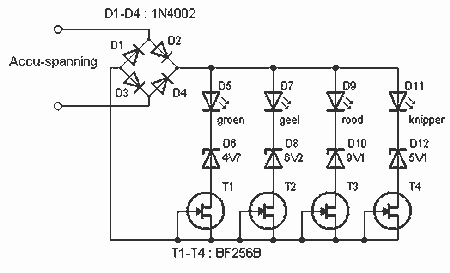
LED Battery indicator
This battery allows the indicator to the car battery voltage monitor. The indicator has four LEDs which indicate power. The more LEDs, the higher the voltage. The last LED is a flashing LED. It comes on when the accuspaning limit...
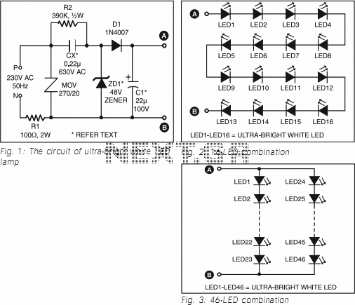
Ultra Bright LED Lamp
This ultra-bright white LED lamp operates on 230V AC with minimal power consumption. It is suitable for illuminating VU meters, SWR meters, and similar applications. Ultra-bright LEDs available in the market are priced between Rs 8 to 15. These LEDs...
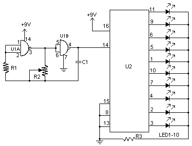
LED Chaser circuit
This schematic represents a version of a simple LED chaser. A 555 timer is not utilized due to its high cost at local electronics stores, which is over $4 CAD. Instead, an oscillator is constructed using two sections of a...
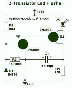
LED Flasher III
This circuit will flash a super-bright LED (5000+ mcd). Good for fake car alarm or other attention-getting device. Component values are not critical; try anything else first from your junk box. Obviously, the 470 ohm resistor (R3) determines the LED's...
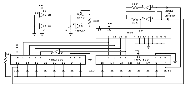
16 Stage Bi-Directional LED Sequencer
The bi-directional sequencer employs a 4-bit binary up/down counter (CD4516) and two "1 of 8 line decoders" (74HC138 or 74HCT138) to produce the widely recognized Nigh.
The bi-directional sequencer circuit is designed to manage the sequencing of outputs based on a...
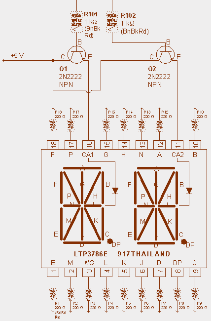
ALPHANUMERIC LED DISPLAY PROJECT
A tiny sandwich flag connected perpendicular to the motor spindle aids observation of how long it takes to complete one full rotation. This worked initially, as each burst from the capacitor barely moved the flag 1/4 of a rotation. As...
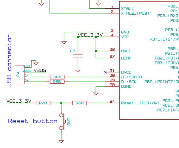
Bicycle LED POV hardware
The microcontroller unit (MCU) will read images from the DataFlash memory via the SPI bus based on the known velocity. It will then send these images to the LED drivers using the SPI bus, controlling the on and off states...
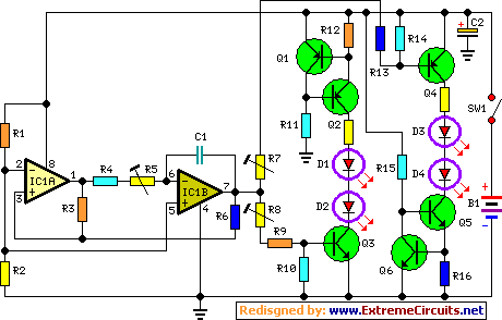
Fading Leds Circuit
This circuit operates two LED strips in pulsing mode, where one LED strip transitions from an off state to gradually lighting up, then dimming, while the other LED strip performs the opposite action. Each strip can consist of 2 to...
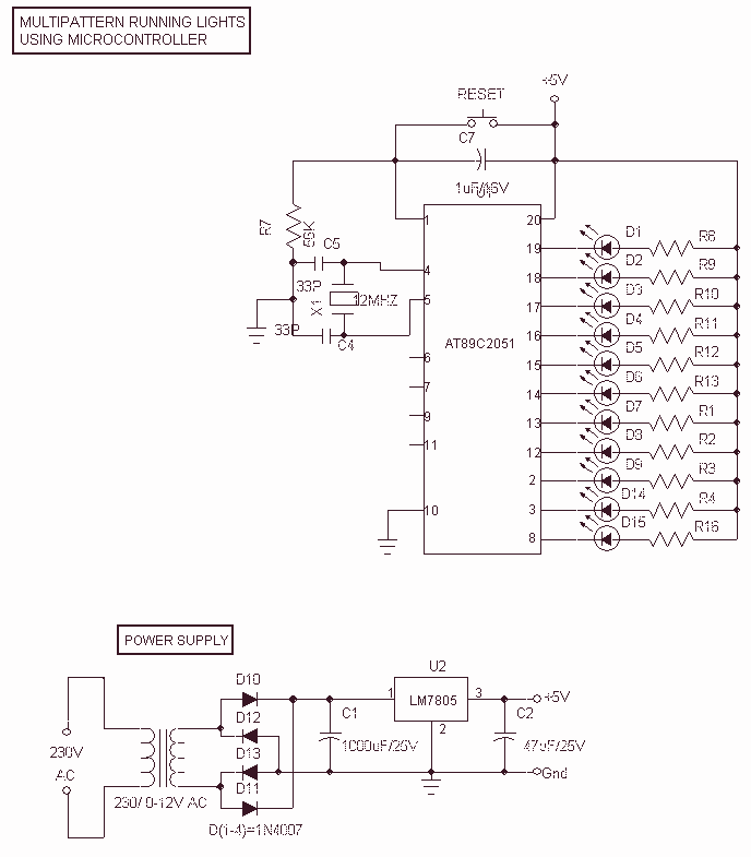
Multipattern Running LEDs
This Project Multi-Pattern Running light is used to generate several designs of Running Lights. We use ten LEDs for display. The designs can be selected by using two switches UP and DOWN. The 8 bit Microcontroller is used to control...