


DIY Plasma Gun v2
#plasma gun
#Tesla coil
#DIY
#high voltage
#homemade
#electronics project
#experimental
#science
#energy
#sparks
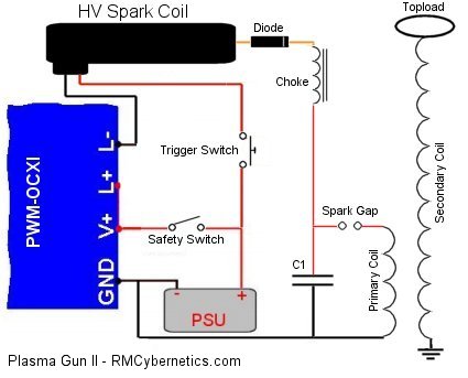
Description: DIY Homemade Plasma Gun. This project demonstrates how to construct a functioning plasma gun. The plasma gun operates using a small Tesla coil.
The DIY homemade plasma gun is an intriguing project that utilizes the principles of plasma generation through high-voltage discharge. At its core, the device is based on a small Tesla coil, which is a type of resonant transformer circuit that produces high-voltage, low-current, high-frequency alternating current electricity. This high-voltage output is essential for creating the plasma effect.
The circuit typically consists of several key components including a power supply, a primary coil, a secondary coil, and a spark gap. The power supply provides the necessary voltage to energize the primary coil. When current flows through the primary coil, it generates a magnetic field that induces a current in the secondary coil due to electromagnetic induction. This process amplifies the voltage, leading to the generation of high-voltage pulses.
The spark gap serves as a switch that allows the current to flow intermittently, creating bursts of energy that ionize the air around the output terminal of the secondary coil. This ionization results in the formation of plasma, which can be visually observed as a bright arc or discharge. The design may also include safety features, such as insulation and protective enclosures, to prevent accidental contact with high-voltage components.
In constructing the plasma gun, careful attention must be paid to component ratings and circuit layout to ensure safe operation. Proper grounding and the use of high-voltage rated materials are critical to prevent electrical hazards. Overall, this project not only showcases the fascinating properties of plasma but also provides an educational experience in the field of high-voltage electronics.DIY Homemade Plasma Gun. Awesome DIY project showing how to make a real working Plasma gun! The plasma gun is based on a small Tesla coil..
The DIY homemade plasma gun is an intriguing project that utilizes the principles of plasma generation through high-voltage discharge. At its core, the device is based on a small Tesla coil, which is a type of resonant transformer circuit that produces high-voltage, low-current, high-frequency alternating current electricity. This high-voltage output is essential for creating the plasma effect.
The circuit typically consists of several key components including a power supply, a primary coil, a secondary coil, and a spark gap. The power supply provides the necessary voltage to energize the primary coil. When current flows through the primary coil, it generates a magnetic field that induces a current in the secondary coil due to electromagnetic induction. This process amplifies the voltage, leading to the generation of high-voltage pulses.
The spark gap serves as a switch that allows the current to flow intermittently, creating bursts of energy that ionize the air around the output terminal of the secondary coil. This ionization results in the formation of plasma, which can be visually observed as a bright arc or discharge. The design may also include safety features, such as insulation and protective enclosures, to prevent accidental contact with high-voltage components.
In constructing the plasma gun, careful attention must be paid to component ratings and circuit layout to ensure safe operation. Proper grounding and the use of high-voltage rated materials are critical to prevent electrical hazards. Overall, this project not only showcases the fascinating properties of plasma but also provides an educational experience in the field of high-voltage electronics.DIY Homemade Plasma Gun. Awesome DIY project showing how to make a real working Plasma gun! The plasma gun is based on a small Tesla coil..
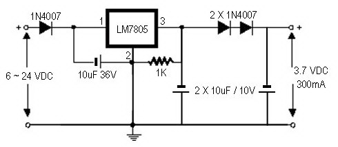
how to convert a 9v battery to 3.7v
A regulator circuit is needed for this DIY project. Familiarity with electronic components, circuitry, the use of a multitester, and a soldering iron is essential. The schematic diagram provided can accept an input voltage ranging from 6 to 24 volts...
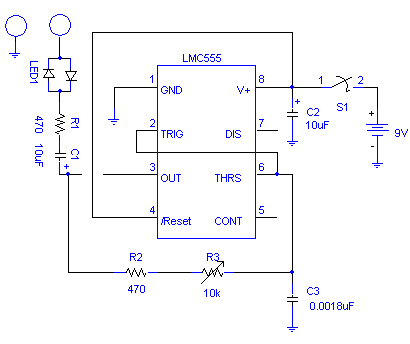
DIY Homemade Tesla Coil Tuner
DIY Homemade Tesla Coil Tuner. Instructions for constructing a Tesla Coil Tuner using readily available components. Determine the resonant frequency of Tesla Coil components.
A Tesla Coil Tuner is an essential tool for optimizing the performance of a Tesla coil by...
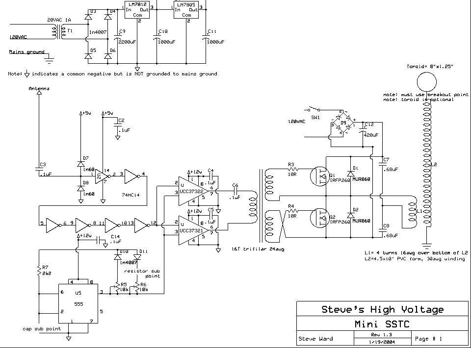
Medium Solid State Tesla Coil
The design is a clone of Steve Ward's MiniSSTC circuit; the schematic is reprinted here with credits to Steve Ward. This circuit performs very well for a low power and simple SSTC. The design is based on Steve's final revised...
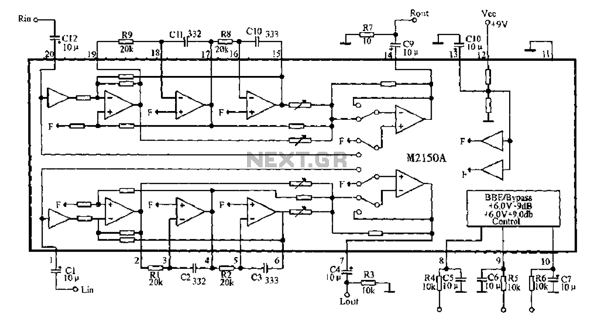
BBE monolithic integrated circuit M2150A
4V flat monitor high voltage power supply circuit diagram. A wide range of 7 to 40V to 5V DC-DC step-down circuit diagram. Light control switch circuit diagram for safety. Circuit 555 constitutes a control circuit diagram for photoelectric applications.
The 4V...
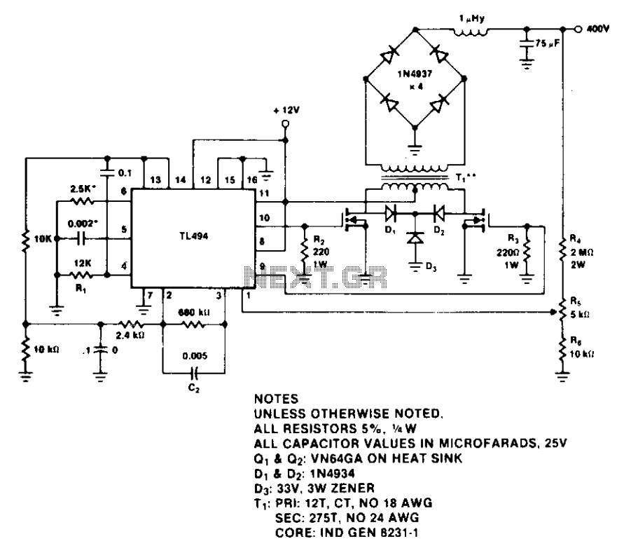
400-Volt 60-watt push-pull power supply
The design provides a regulated output of 400 V and 60 W. The TL494 switching regulator controls the operating frequency and output voltage regulation. Resistor R1 and capacitor C1 set the switching frequency, which is approximately 0.5 to 100 kHz...
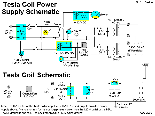
TESLA PROJECT BIG COIL
This section details the construction and testing of a medium to large class Tesla coil. A new, larger coil has been redesigned and constructed for maximum efficiency, featuring a secondary coil over 6 inches in diameter and capable of operating...
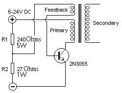
High Voltage Solid State Flyback Driver
Fully illustrated and schematized plans for a high-performance, easy-to-build transistorized high voltage flyback driver.
The high voltage flyback driver circuit is designed to efficiently convert low voltage DC into high voltage pulses suitable for driving flyback transformers. The circuit typically utilizes...
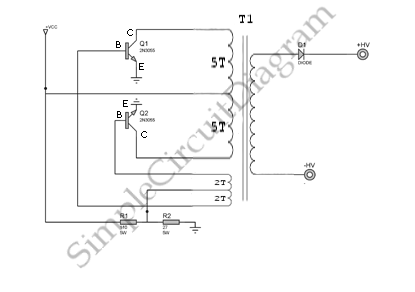
High Voltage Inverter
This is a simple high-voltage inverter circuit. It uses an NPN transistor type 2N3055. This circuit is designed to invert low voltage to high voltage.
The high-voltage inverter circuit utilizing the 2N3055 NPN transistor serves as an effective means to convert...
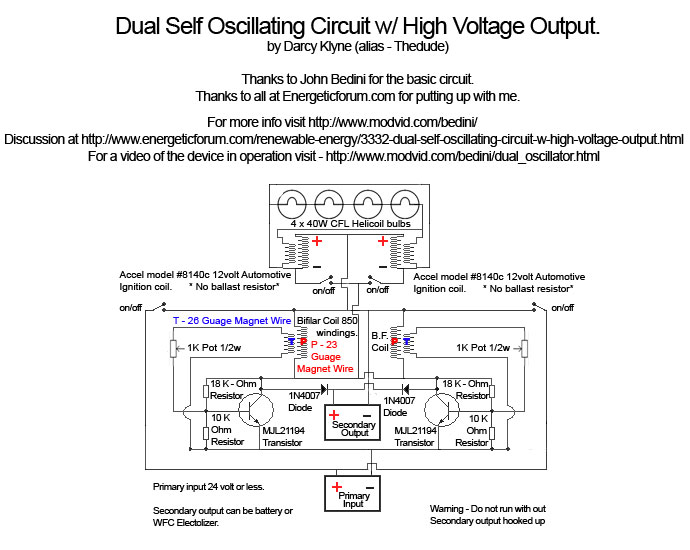
Bedini Self Oscillator High Voltage Output
A Tesla pancake coil is connected in series with a bifilar wound coil to generate resonance and a sharp gradient discharge, which creates a vacuum flux. The circuit operates with a CFL at approximately 0.07 amps and 12.42 volts, consuming...