


firework launcher
#firework ignition
#DIY project
#Radio Shack components
#Walmart components
#ignition system
#hobby electronics
#safety circuits
#remote ignition
#high voltage
#pyrotechnics
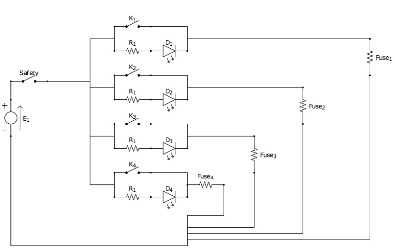
Description: An article detailing the construction of a firework ignition system using components acquired from Walmart and Radio Shack.
The firework ignition system is designed to safely and effectively initiate fireworks using common electronic components. The system typically consists of a power source, a triggering mechanism, and an ignition circuit.
The power source can be a battery or a DC power supply, providing the necessary voltage and current to activate the ignition system. A common choice for such applications is a 9V battery, which offers a suitable voltage level for most ignition circuits.
The triggering mechanism may involve a simple switch or a more sophisticated control system, such as a remote control or a timer circuit, allowing for precise ignition timing. For remote operation, a wireless RF module can be employed, enabling the user to ignite the fireworks from a safe distance.
The ignition circuit usually includes a resistor, a capacitor, and an igniter. The igniter is often a commercially available electric match or a fuse, which ignites when sufficient current passes through it. The resistor limits the current to protect sensitive components, while the capacitor can be used to store energy and provide a quick discharge to ensure reliable ignition.
Safety precautions are paramount when constructing and using a firework ignition system. All components should be rated for the voltage and current they will handle, and the system should be tested in a controlled environment before actual use. Proper insulation and secure connections are essential to prevent accidental ignition and ensure the safety of the operator and the surrounding area.
Overall, the design and implementation of a firework ignition system require careful consideration of the components used, their arrangement, and adherence to safety standards to achieve effective and safe operation.An article describing how I made a firework ignition system out of a few things I picked up at Walmart and Radio Shack..
The firework ignition system is designed to safely and effectively initiate fireworks using common electronic components. The system typically consists of a power source, a triggering mechanism, and an ignition circuit.
The power source can be a battery or a DC power supply, providing the necessary voltage and current to activate the ignition system. A common choice for such applications is a 9V battery, which offers a suitable voltage level for most ignition circuits.
The triggering mechanism may involve a simple switch or a more sophisticated control system, such as a remote control or a timer circuit, allowing for precise ignition timing. For remote operation, a wireless RF module can be employed, enabling the user to ignite the fireworks from a safe distance.
The ignition circuit usually includes a resistor, a capacitor, and an igniter. The igniter is often a commercially available electric match or a fuse, which ignites when sufficient current passes through it. The resistor limits the current to protect sensitive components, while the capacitor can be used to store energy and provide a quick discharge to ensure reliable ignition.
Safety precautions are paramount when constructing and using a firework ignition system. All components should be rated for the voltage and current they will handle, and the system should be tested in a controlled environment before actual use. Proper insulation and secure connections are essential to prevent accidental ignition and ensure the safety of the operator and the surrounding area.
Overall, the design and implementation of a firework ignition system require careful consideration of the components used, their arrangement, and adherence to safety standards to achieve effective and safe operation.An article describing how I made a firework ignition system out of a few things I picked up at Walmart and Radio Shack..
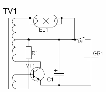
high voltage power supply circuit for fluorescent light
High-voltage power supply circuit for fluorescent light power supply. Refer to that page for an explanation of the related circuit diagram.
The high-voltage power supply circuit designed for fluorescent lights typically consists of several key components that work together to convert...
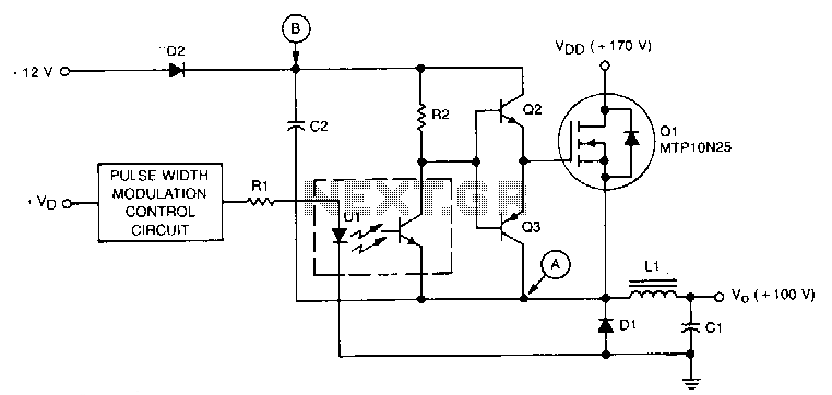
High-voltage-bucking-regulator
This circuit is essentially a classic buck regulator that utilizes a TMOS N-channel power FET for the chopper and generates its own supply for gate control. The unique feature of this circuit is its method for creating a separate supply...
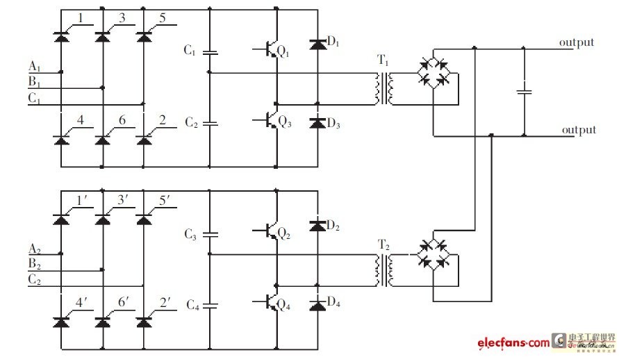
High-pressure direct current power supply scheme of the new low ripple
The high-pressure direct current power supply has become increasingly widespread. This system outputs in parallel with double-channel power to achieve low ripple direct current. In situations where gas switching tube frequency is limited, this method can generate low ripple direct...
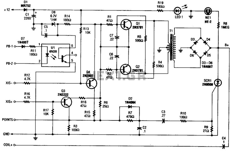
Cd Ignition System For Autos Circuit
At the core of the CD4-MX is an astable multivibrator, constructed using transistors Q1 and Q2, which drives step-up transformer T1. The output from T1 is rectified by diodes D3 to D6 and utilized to charge capacitor C4. Upon the...
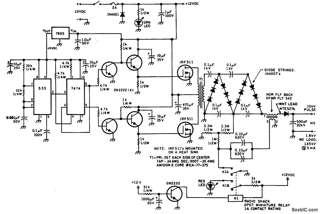
HELIUM NEON LASER PS WITH HV PULSE IGNITION
The helium-neon laser requires two voltages: one in the range of 10 kV to initiate the laser, which is turned off once the discharge begins, and a lower-voltage power supply to sustain the discharge. The circuit diagram illustrates a method...
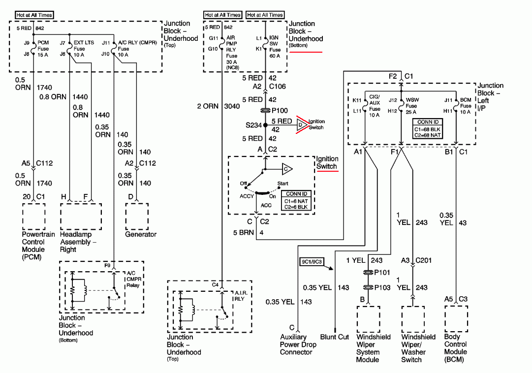
2001 monte carlo: no wipers noturn signals none of the dash lights
A 2001 Monte Carlo is experiencing electrical issues where only the lights are functioning. The radio, wipers, turn signals, and dash lights do not operate when the ignition key is turned. It has been suggested that the computer system may...
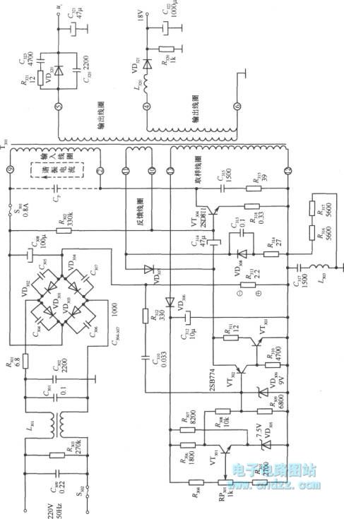
High voltage switching stabilized voltage supply circuit
A high voltage switching stabilized voltage supply circuit is illustrated in the diagram. This is the switching power supply for an 80P type color television. It utilizes auto-excitation and a PWM circuit. The output is isolated from the power system,...
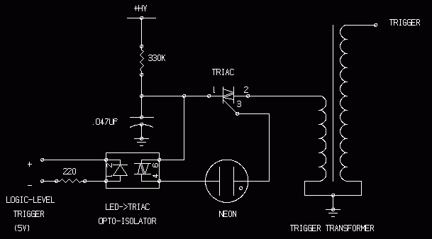
Various Schematics and Diagrams
Energy storage capacitors in even the smallest disposable camera flash powered by a 1.5 V AA battery can be hazardous under certain conditions. Line-powered devices, regardless of size, may present additional risks due to high power at high voltage and...
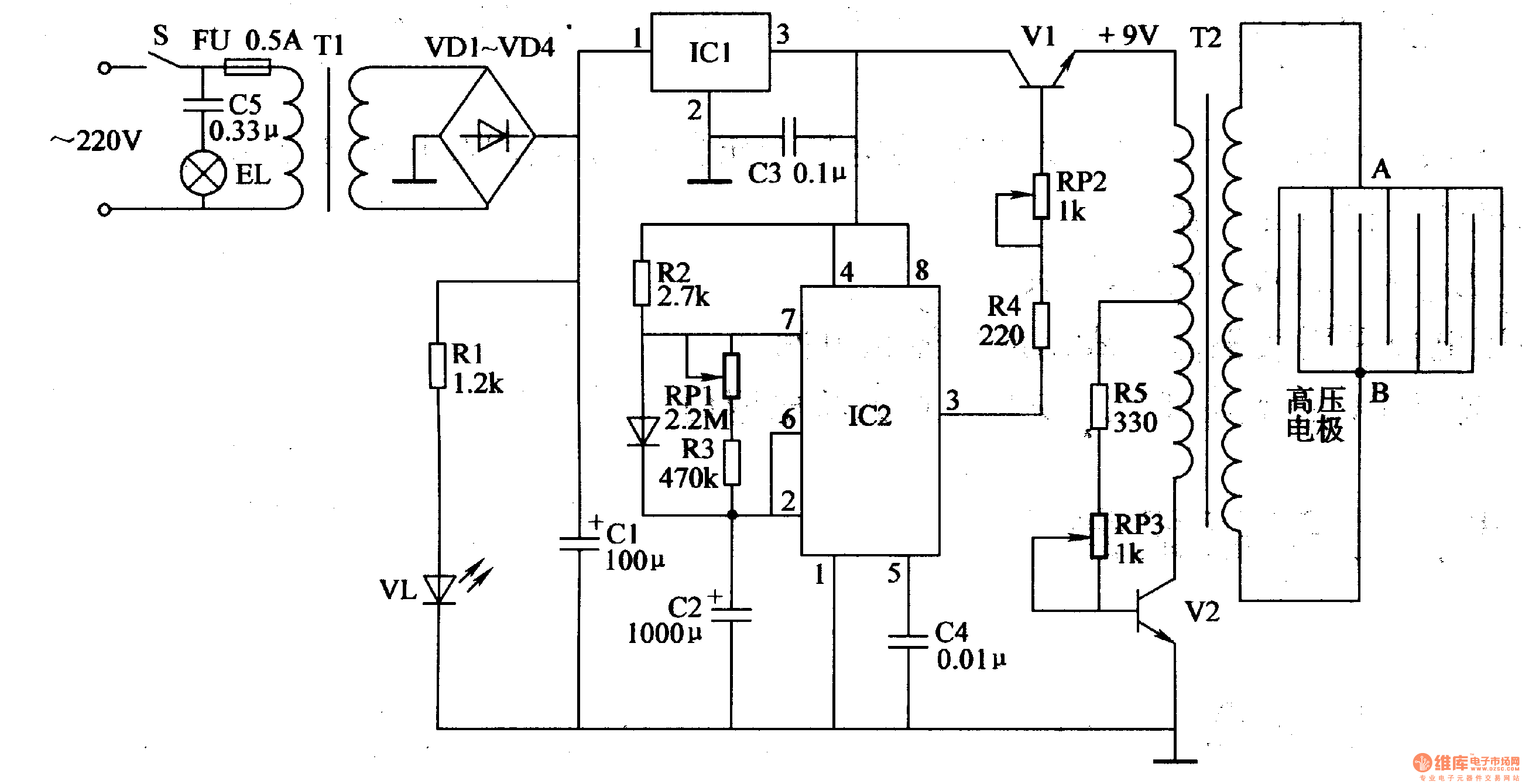
Electronic Pest Killing Lamp
Working Principle: The circuit, as illustrated in figure 4-187, is composed of three main components: the power circuit, the pulse oscillator, and the high voltage generator. The power circuit includes components S, FU, TI, VD1-VD4, C1, C3, IC1, R1, and...