


Flame-ignitor
#flame-ignitor
#gas ignitor
#spark generator
#SCR
#PUT
#transformer
#capacitor
#resistor
#trigger circuit
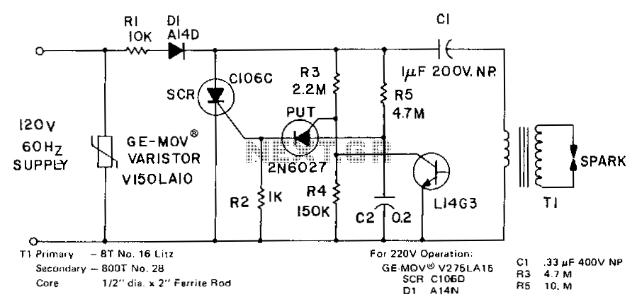
Description: The spark generated by the circuit is suitable for a gas ignitor. Capacitor C1 is charged through R1 and D1 towards peak line voltage. Concurrently, C2 is being charged at a slower rate through R5. When the charge on C2 is sufficient to trigger the Programmable Unijunction Transistor (PUT), the Silicon Controlled Rectifier (SCR) is activated, providing a rapid discharge path for C1 through the transformer primary. The SCR is triggered approximately 20 times per second with the specified component values. Additionally, the L14G3 functions as a flame sensor. Once ignition is achieved and detected by the photodetector, the low voltage at Vc8 prevents further triggering of the SCR.
The described circuit operates as a gas ignitor, utilizing a combination of capacitors, resistors, and diodes to create a high-voltage spark necessary for ignition. The charging of capacitor C1 occurs rapidly through resistor R1 and diode D1, allowing it to reach peak line voltage efficiently. Simultaneously, capacitor C2 is charged more slowly through resistor R5, creating a delay that enables the system to regulate the ignition process.
The key component in this circuit is the Programmable Unijunction Transistor (PUT), which acts as a control element. Once the voltage across capacitor C2 reaches a predetermined threshold, the PUT triggers the SCR. This action creates a low-resistance path for the discharge of capacitor C1, allowing the energy stored in C1 to flow through the primary winding of the transformer, generating a high-voltage spark necessary for igniting gas.
The triggering frequency of the SCR, approximately 20 times per second, indicates a repetitive cycle of charging and discharging that maintains consistent ignition capability. The use of L14G3 as a flame sensor enhances the safety and reliability of the system. When the photodetector senses successful ignition, it generates a low voltage at Vc8. This low voltage effectively disables further SCR triggering, preventing unnecessary discharge and potential hazards associated with continuous sparking.
Overall, this circuit design is an efficient and effective solution for gas ignition applications, combining rapid spark generation with safety features to ensure reliable operation. The careful selection of components and their values plays a crucial role in achieving the desired performance and functionality of the ignitor system.The spark developed by the circuit is suitable for a gas ignitor. Capacitor Cl is charged through Rl and Dl toward peak line voltage. C2 is simultaneously being charged at a slower rate through R5. When the charge on C2 is sufficient.to trigger the PUT, the SCR is triggered on, providing a rapid discharge path for Cl through the transformer primary. The SCR is triggered about 20 times per second with the component values shown. The Ll4G3 serves as a flame sensor. When ignition is achieved and sensed by the photodetector, the low Vc8 prevents further SCR triggering.
The described circuit operates as a gas ignitor, utilizing a combination of capacitors, resistors, and diodes to create a high-voltage spark necessary for ignition. The charging of capacitor C1 occurs rapidly through resistor R1 and diode D1, allowing it to reach peak line voltage efficiently. Simultaneously, capacitor C2 is charged more slowly through resistor R5, creating a delay that enables the system to regulate the ignition process.
The key component in this circuit is the Programmable Unijunction Transistor (PUT), which acts as a control element. Once the voltage across capacitor C2 reaches a predetermined threshold, the PUT triggers the SCR. This action creates a low-resistance path for the discharge of capacitor C1, allowing the energy stored in C1 to flow through the primary winding of the transformer, generating a high-voltage spark necessary for igniting gas.
The triggering frequency of the SCR, approximately 20 times per second, indicates a repetitive cycle of charging and discharging that maintains consistent ignition capability. The use of L14G3 as a flame sensor enhances the safety and reliability of the system. When the photodetector senses successful ignition, it generates a low voltage at Vc8. This low voltage effectively disables further SCR triggering, preventing unnecessary discharge and potential hazards associated with continuous sparking.
Overall, this circuit design is an efficient and effective solution for gas ignition applications, combining rapid spark generation with safety features to ensure reliable operation. The careful selection of components and their values plays a crucial role in achieving the desired performance and functionality of the ignitor system.The spark developed by the circuit is suitable for a gas ignitor. Capacitor Cl is charged through Rl and Dl toward peak line voltage. C2 is simultaneously being charged at a slower rate through R5. When the charge on C2 is sufficient.to trigger the PUT, the SCR is triggered on, providing a rapid discharge path for Cl through the transformer primary. The SCR is triggered about 20 times per second with the component values shown. The Ll4G3 serves as a flame sensor. When ignition is achieved and sensed by the photodetector, the low Vc8 prevents further SCR triggering.
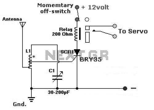
Very Simple Radio Control (R/C)
The diagram illustrates a simple and efficient receiver designed for controlling garage doors, starter motors, alarms, warning systems, and various other applications. The SCR utilized in this circuit features an exceptionally low trigger current of 30 µA.
The circuit operates as...
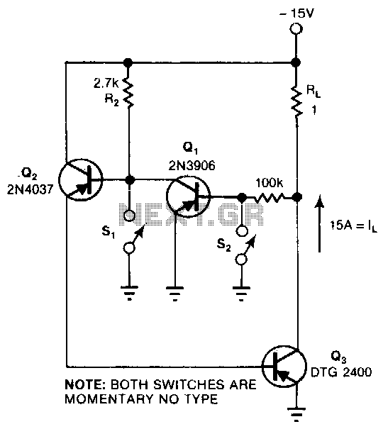
Scr-replacing-latching-switch
This circuit provides the turn-on characteristics of a Silicon Controlled Rectifier (SCR) but allows for easy turn-off. The switch consists of three transistors with decreasing current ratings: Q3 has a high current rating, while Q2 has a medium rating. The...
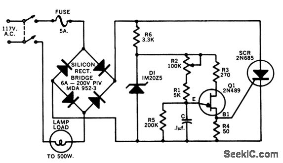
SCR LIGHT DIMMER
Provides full range of brightness control for up to 500 watts of lamps. The UJT Q1 generates turn-on pulses for SCR-L. Stern, "Thyristors Provide New Opportunities for Electronic Applications in the Home," Motorola Application Note AN-141, Dec. 1965.
The described circuit...
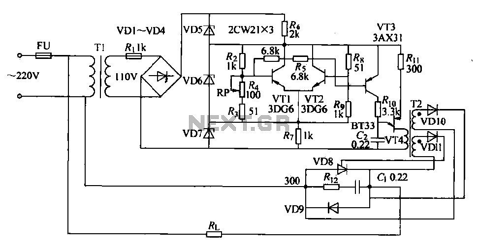
SCR furnace temperature regulating circuit
The circuit consists of two differential amplifier transistors configured with a voltage dividing type bias circuit, measuring the resistance of four arms in a bridge configuration. The product includes a platinum resistance sensor, which exhibits an increase in resistance with...
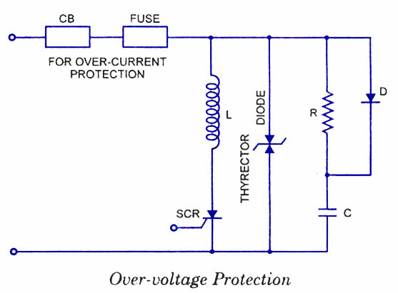
SCR Protection Circuits
Silicon Controlled Rectifiers (SCRs) are sensitive to high voltage, over-current, and transients. To ensure satisfactory and reliable operation, they must be protected against such abnormal operating conditions. Due to the complexity and cost of protection mechanisms, devices with ratings higher...
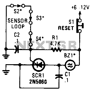
Closed-Loop Alarm Circuit
A string of three series-connected, normally closed switches is connected across the gate of a silicon-controlled rectifier (SCR). When one switch opens, the SCR is triggered through resistor R1, activating an alarm. The alarm is designed to be of the...
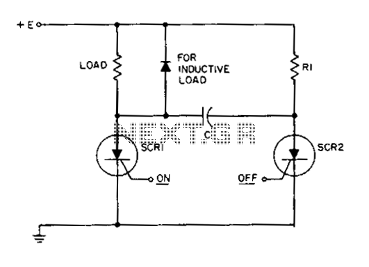
Dc static switch
This circuit is a static SCR switch designed for use in a DC circuit. When a low-power signal is applied to the gate of SCR1, this SCR is triggered, allowing voltage to be applied to the load. The right plate...
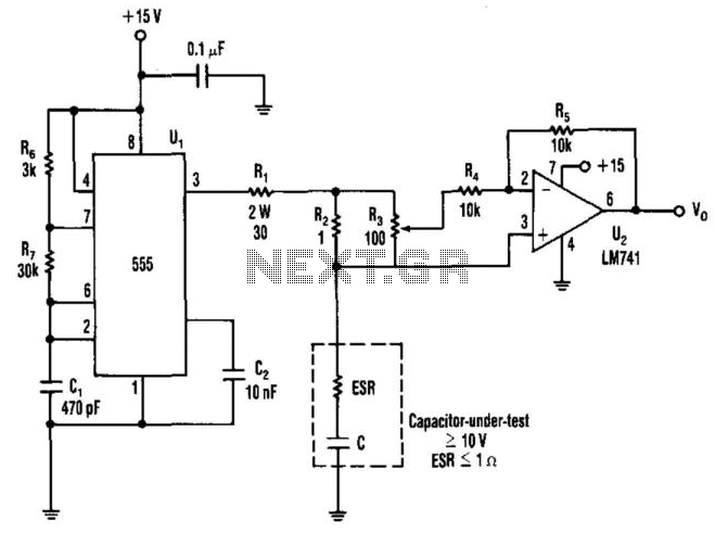
Capacitor Esr Measurer
The equivalent series resistance (ESR) of a capacitor can be measured using this circuit and an AC voltmeter. It functions as a 50-kHz square-wave generator, driving a current waveform of approximately ±180 mA through the capacitor-under-test via resistors R1 and...
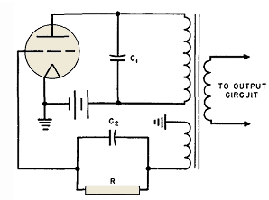
Electronic Transformer Coupled Oscillators
The transformer OCL and capacitor C1 create a tank circuit, which is coupled with sufficient turns to drive the grid in the lower left-hand winding. The output circuit is connected through a separate winding. For optimal waveform characteristics in such...