


Introducing DOGZILLA
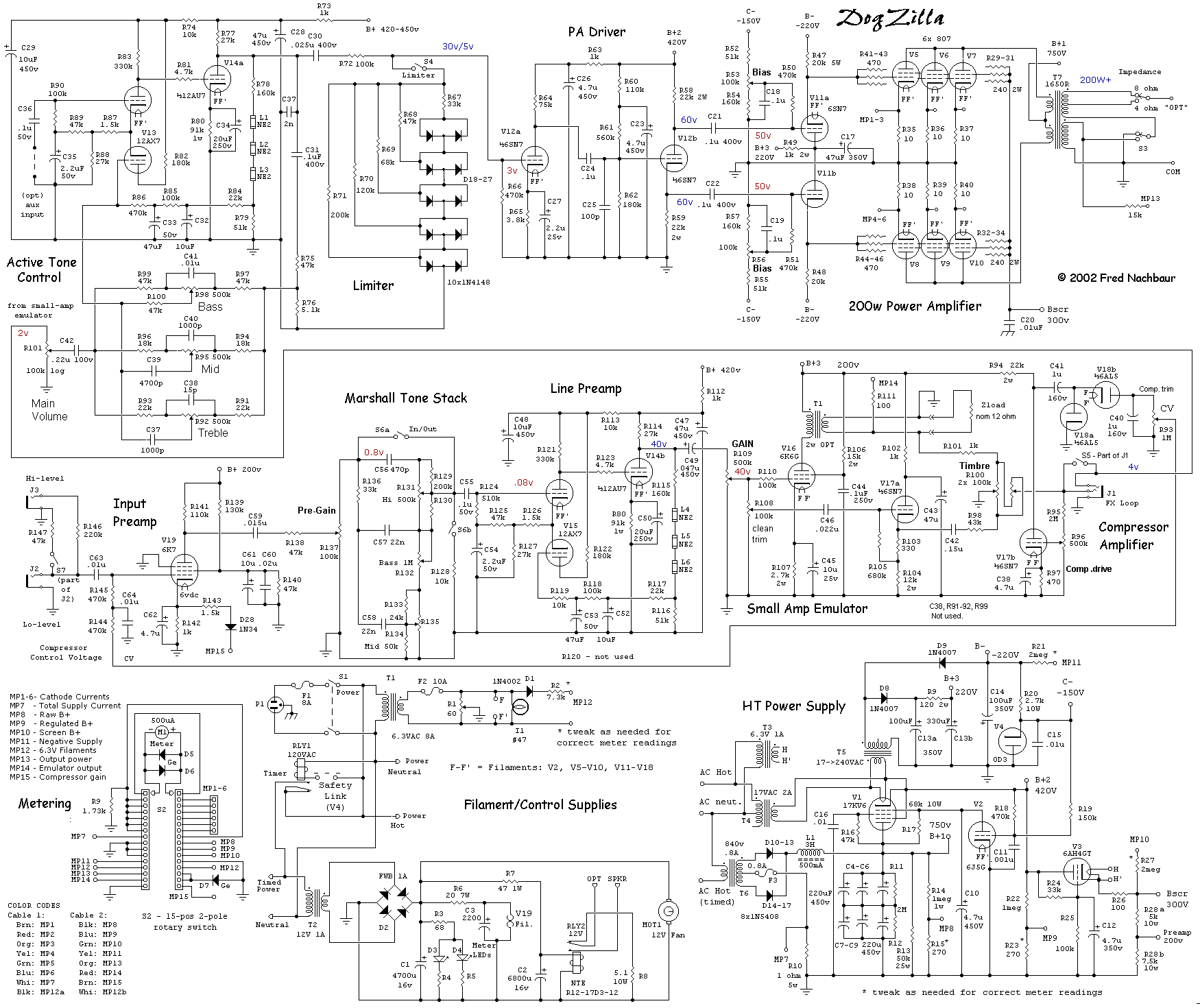
Description: The chassis layout has been designed, and the 17" x 14" x 3" steel chassis is ready for drilling and hole-cutting. There is no backing off now; Dogzilla will live! It is actually starting to resemble a piece of equipment. Most of the chassis parts are mounted, except for the iron. The gold vent-hole screens were acquired from a local shop. The iron and the metering switch box are now installed. On the far left is a 5V filament transformer for rectifiers and the B+ power supply filter choke. In the center is a balanced line input transformer. On the right are two Hammond 1650R output transformers (the older style, before the addition of knock-outs in the bells), along with a 6V filament transformer and a small "amp emulator" output transformer, which is concealed by the meter box. Underneath are four additional transformers (filament supplies for the pass regulator, control supply, and auxiliary B+ and negative bias supply). Almost all of the mechanical work is complete, alleviating the issue of metal filings and shavings. Underneath, there are twelve 8-prong terminal strips, the bias control board, and barrier strips for power and speaker signal distribution, all set for the extensive wiring task ahead. A preview of the completed project is available. The only desired change in the layout would be relocating the input section to the opposite side, away from the high-tension power supply. Shielding and insulation are anticipated to mitigate interference from the input components. All mechanical work and much of the wiring have been finalized. The originally planned 866AX rectifiers were omitted due to an arcing issue with the filament transformer. Individual cathode bias adjustments were also discarded as they proved to be more troublesome than beneficial. Instead, a small "monitor" speaker salvaged from a PC multimedia speaker has been integrated, accompanied by a large dropping resistor to facilitate debugging while using a dummy load. All power supplies, metering, power amplifier, and driver sections have been completed and tested. A burn test (one hour at continuous 200W RMS into a dummy load) was successful, with no smoke or flames. Although it is unlikely that anyone will construct an exact replica of Dogzilla, many circuit details and other information may benefit DIY amplifier builders. Updates have been made to the article, including Part 6, which details the active tone control section. The block diagram has been slightly modified but not yet updated, as it remains subject to possible changes. Part 7 discusses the small-amp emulator and compressor option. Part 8 covers the bypassable "Marshall" tone stack and line amplifier, while Part 9 addresses the variable-mu pentode input stage. The planned low-impedance input was scrapped due to excessive hum, even with a shielded mic transformer on the chassis. Although the project is nominally complete, fine-tuning remains, particularly regarding hum issues, which may necessitate the addition of mu-metal shielding to address magnetic induction from the power transformer and filter choke. The necessity of dual output transformers has been reconsidered, as Dogzilla functions adequately with a single Hammond 1650R, demonstrating that these transformers are conservatively rated. The amplifier consistently delivers over 200 watts from a transformer rated for 100 watts (designed for hi-fi use) without overheating. Part 4 has been updated to reflect this change, freeing up chassis space, which may accommodate a tremolo or other effects board. Shielding has been added around the dual preamp board and the tubes on that board.
The described chassis layout represents a robust and well-thought-out design intended for a high-power amplifier. The dimensions of the steel chassis—17 inches by 14 inches by 3 inches—provide ample space for the necessary components while maintaining structural integrity. Key components include a 5V filament transformer, which is critical for powering the rectifiers, and a B+ power supply filter choke that ensures smooth operation of the high voltage supply. The inclusion of balanced line input transformers is indicative of a design focused on minimizing noise and ensuring high-quality audio reproduction.
The use of Hammond 1650R output transformers highlights a preference for reliability and performance, particularly in high-power applications. These transformers are known for their durability and efficiency, which is essential for amplifying audio signals without distortion. The careful arrangement of transformers and other components within the chassis not only facilitates effective thermal management but also minimizes electromagnetic interference, which is crucial for maintaining audio fidelity.
Wiring and connections are organized through the use of terminal strips and barrier strips, which streamline the assembly process and enhance serviceability. The decision to include a monitor speaker for debugging purposes demonstrates a practical approach to troubleshooting during the development phase.
Overall, this chassis layout reflects a comprehensive understanding of amplifier design principles, with considerations for both performance and ease of assembly. The ongoing adjustments and updates to the design, such as the removal of unnecessary components and the addition of shielding, indicate a commitment to achieving optimal performance in the final product.The chassis layout has been designed, and the 17" x 14" x 3" steel chassis is ready for drilling and hole-cutting. There`s no backing off now, Dogzilla will live! It`s actually starting to look like a piece of gear. Most of the chassis parts mounted, except for the iron. Those pretty gold vent-hole screens came from the local paraphernalia shop. S ure got a funny look when I asked for 20 of them. The iron and the metering switch box are now mounted. Far left: 5V filament transformer for rectifiers, and the B+ power supply filter choke. Center: balanced line input transformer. Right: two Hammond 1650R output transformers (the old style, before they started putting those stupid knock-outs in the bells). Also the 6V filament transformer, and the wee "small amp emulator" OPT (hidden by the meter box). Underneath are four more transformers (filament supplies for pass regulator, control supply, and auxiliary B+ and negative bias supply).
Finally, almost all of the ruddy mechanical stuff complete. I was getting tired of metal filings and shavings everywhere. Underneath, there`s a dozen 8-prong terminal strips, the bias control board, and barrier strips for power and speaker signal distribution, ready to start the major task of wiring it all up. Here`s a sneak preview of what it will look like when complete. The only thing I`d change in the layout would be to move the input section to the other side, away from the HT power supply.
(I`m hoping to get away with it by shielding and insulating the input stuff within an inch of its life. ) All the mechanics, and much of the wiring complete. Opted out of the 866AX rectifiers originally planned, mainly because my filament transformer arced over and I couldn`t be bothered to replace it.
Also dropped the individual cathode bias adjustments, which turned out to be more of a nuisance than they were worth. In their place is a small "monitor" speaker scrounged from a PC "multimedia" speaker, with a large dropping resistor to aid in debugging while on the big dummy load.
All the power supplies, metering, PA, and driver sections complete and tested. Burn-test (one hour at continuous 200W RMS into a dummy load) successful, no smoke or flames! Click on the "start" link below to follow through the circuit descriptions. While I think it unlikely that anyone will ever build an exact copy of DogZilla, there are many circuit details and other information that may be of use to DIY amplifier builders. If you`d like to see more pix of Dogzilla, click "more pictures" button. Recent addition to the article is Part 6, detailing the active tone control section. Block diagram modified slightly (not updated yet, as is still subject to possible change). This is detailed in Part 7, detailing the small-amp emulator and compressor option. Part 8 details the bypassable "Marshall" tone stack, and line amplifier. Part 9 covers the variable-mu pentode input stage. Scrapped the planned lo-z input; even a shielded mic transformer on the chassis picks up so much hum that the notion was written of as a Bad Idea.
While the project is nominally complete, there is the inevitable fine-tuning left to do. Particularly, the amp still has hum issues; I suspect I`ll have to add mu-metal shielding, since much of it appears to be the result of magnetic induction from the power transformer and filter choke. I found that the doubled-up output transformers really isn`t necessary. Dogzilla works just fine with "just" a single Hammond 1650R. Just goes to show how conservatively rated these things are; I`m still getting well in excess of 200 watts out of a single transformer rated at 100 watts (albeit for hi-fi use), with no sign of overheating.
Woohoo! Part 4 has been updated accordingly. Freed up chassis space! (Hm. maybe a tremolo or other effects board might fit there. ) Added shielding around the dual preamp board, and on the tubes on that board. Part 7 has been updated somewh
The described chassis layout represents a robust and well-thought-out design intended for a high-power amplifier. The dimensions of the steel chassis—17 inches by 14 inches by 3 inches—provide ample space for the necessary components while maintaining structural integrity. Key components include a 5V filament transformer, which is critical for powering the rectifiers, and a B+ power supply filter choke that ensures smooth operation of the high voltage supply. The inclusion of balanced line input transformers is indicative of a design focused on minimizing noise and ensuring high-quality audio reproduction.
The use of Hammond 1650R output transformers highlights a preference for reliability and performance, particularly in high-power applications. These transformers are known for their durability and efficiency, which is essential for amplifying audio signals without distortion. The careful arrangement of transformers and other components within the chassis not only facilitates effective thermal management but also minimizes electromagnetic interference, which is crucial for maintaining audio fidelity.
Wiring and connections are organized through the use of terminal strips and barrier strips, which streamline the assembly process and enhance serviceability. The decision to include a monitor speaker for debugging purposes demonstrates a practical approach to troubleshooting during the development phase.
Overall, this chassis layout reflects a comprehensive understanding of amplifier design principles, with considerations for both performance and ease of assembly. The ongoing adjustments and updates to the design, such as the removal of unnecessary components and the addition of shielding, indicate a commitment to achieving optimal performance in the final product.The chassis layout has been designed, and the 17" x 14" x 3" steel chassis is ready for drilling and hole-cutting. There`s no backing off now, Dogzilla will live! It`s actually starting to look like a piece of gear. Most of the chassis parts mounted, except for the iron. Those pretty gold vent-hole screens came from the local paraphernalia shop. S ure got a funny look when I asked for 20 of them. The iron and the metering switch box are now mounted. Far left: 5V filament transformer for rectifiers, and the B+ power supply filter choke. Center: balanced line input transformer. Right: two Hammond 1650R output transformers (the old style, before they started putting those stupid knock-outs in the bells). Also the 6V filament transformer, and the wee "small amp emulator" OPT (hidden by the meter box). Underneath are four more transformers (filament supplies for pass regulator, control supply, and auxiliary B+ and negative bias supply).
Finally, almost all of the ruddy mechanical stuff complete. I was getting tired of metal filings and shavings everywhere. Underneath, there`s a dozen 8-prong terminal strips, the bias control board, and barrier strips for power and speaker signal distribution, ready to start the major task of wiring it all up. Here`s a sneak preview of what it will look like when complete. The only thing I`d change in the layout would be to move the input section to the other side, away from the HT power supply.
(I`m hoping to get away with it by shielding and insulating the input stuff within an inch of its life. ) All the mechanics, and much of the wiring complete. Opted out of the 866AX rectifiers originally planned, mainly because my filament transformer arced over and I couldn`t be bothered to replace it.
Also dropped the individual cathode bias adjustments, which turned out to be more of a nuisance than they were worth. In their place is a small "monitor" speaker scrounged from a PC "multimedia" speaker, with a large dropping resistor to aid in debugging while on the big dummy load.
All the power supplies, metering, PA, and driver sections complete and tested. Burn-test (one hour at continuous 200W RMS into a dummy load) successful, no smoke or flames! Click on the "start" link below to follow through the circuit descriptions. While I think it unlikely that anyone will ever build an exact copy of DogZilla, there are many circuit details and other information that may be of use to DIY amplifier builders. If you`d like to see more pix of Dogzilla, click "more pictures" button. Recent addition to the article is Part 6, detailing the active tone control section. Block diagram modified slightly (not updated yet, as is still subject to possible change). This is detailed in Part 7, detailing the small-amp emulator and compressor option. Part 8 details the bypassable "Marshall" tone stack, and line amplifier. Part 9 covers the variable-mu pentode input stage. Scrapped the planned lo-z input; even a shielded mic transformer on the chassis picks up so much hum that the notion was written of as a Bad Idea.
While the project is nominally complete, there is the inevitable fine-tuning left to do. Particularly, the amp still has hum issues; I suspect I`ll have to add mu-metal shielding, since much of it appears to be the result of magnetic induction from the power transformer and filter choke. I found that the doubled-up output transformers really isn`t necessary. Dogzilla works just fine with "just" a single Hammond 1650R. Just goes to show how conservatively rated these things are; I`m still getting well in excess of 200 watts out of a single transformer rated at 100 watts (albeit for hi-fi use), with no sign of overheating.
Woohoo! Part 4 has been updated accordingly. Freed up chassis space! (Hm. maybe a tremolo or other effects board might fit there. ) Added shielding around the dual preamp board, and on the tubes on that board. Part 7 has been updated somewh
dyi setup and debugging guide
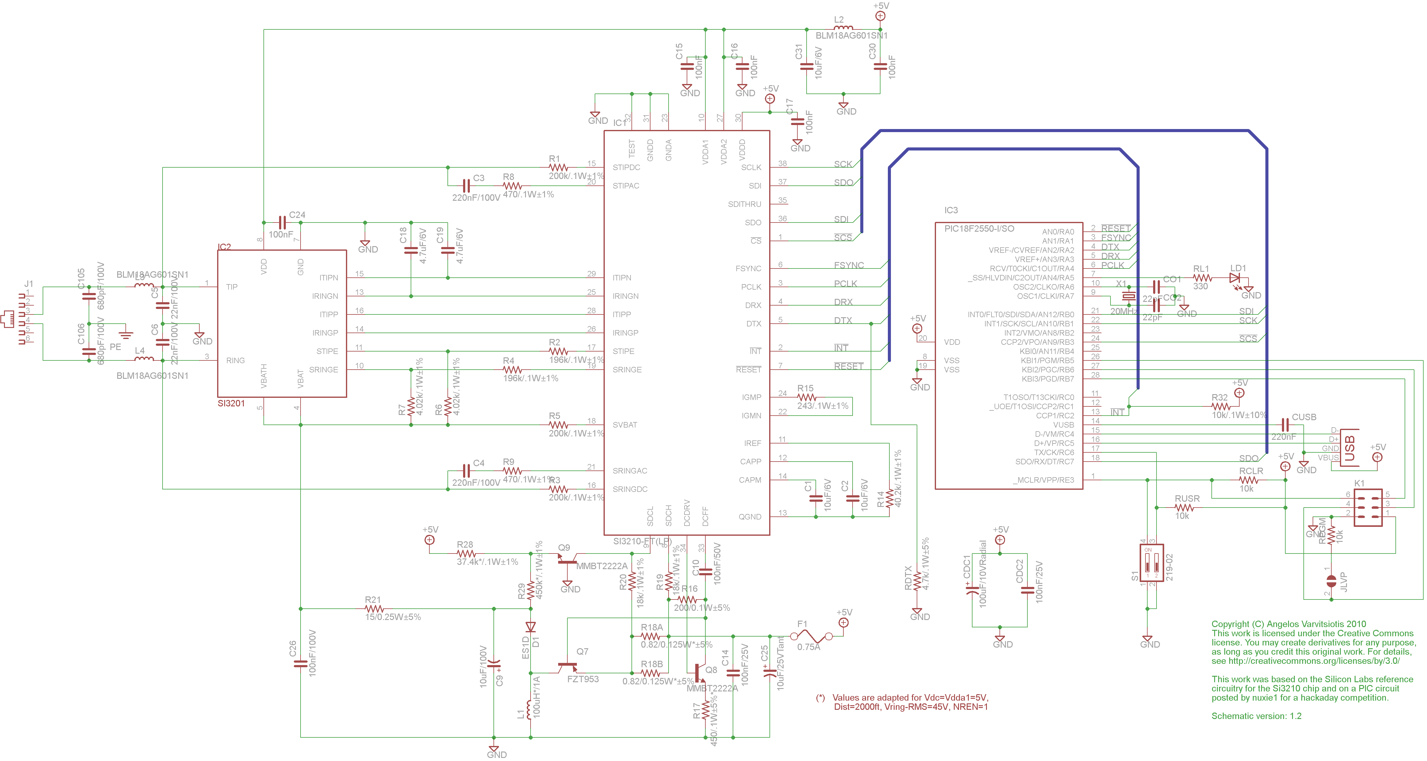
This page discusses the differences between assembled Open USB FXS dongle boards and DIY boards. While the assembled boards are fully tested and quality control approved, DIY boards may encounter various issues during assembly. Fortunately, most of these issues can...
MePADS
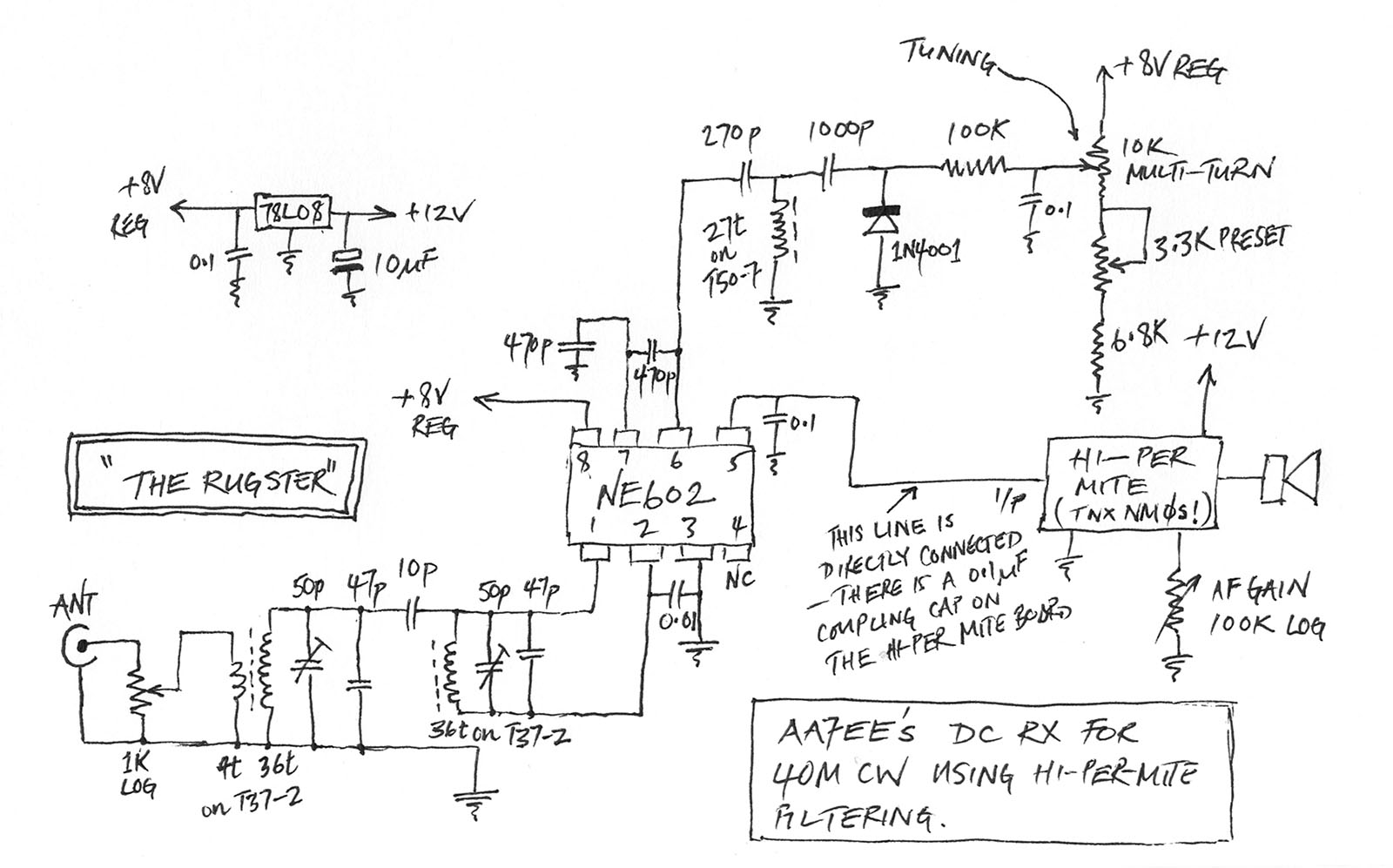
If you are considering building the Desert Ratt 2, it is advisable to read all the accompanying text, as it contains relevant construction details. Engaging with the comments and replies can also provide additional insights, as previous blog posts have...
Glue stck torch
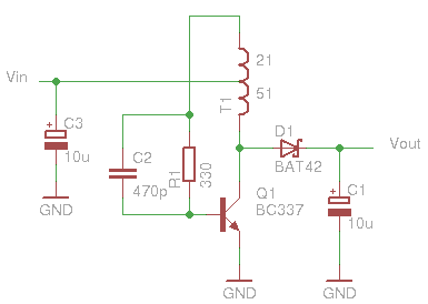
This project, developed around 2005, involves constructing a torch using a glue stick, which conveniently accommodates an AA battery within its plastic casing. To create a functional battery holder, contacts for both the positive and negative connections are necessary. The...

turret diy
For maximum mini-security, this RC Tupperware Turret delivers a formidable deterrent against food theft. While it lacks motion sensors, potential food thieves will think twice before attempting to swipe baked goods. This 11-hour project, designed by Chris of PyroElectro, emphasizes...
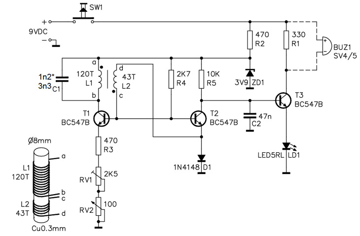
Homemade Metal Detector Kit
A simple home project can quickly become problematic if it encounters electric cables, gas, or water pipes, or the central heating system. Using a metal detector allows one to check for metal objects within walls, ceilings, or floors beforehand. An...
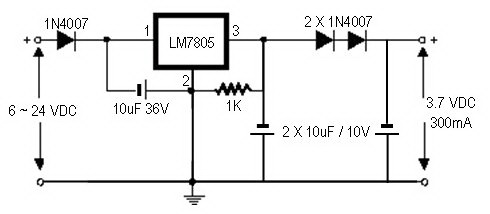
how to convert a 9v battery to 3.7v
A regulator circuit is needed for this DIY project. Familiarity with electronic components, circuitry, the use of a multitester, and a soldering iron is essential. The schematic diagram provided can accept an input voltage ranging from 6 to 24 volts...
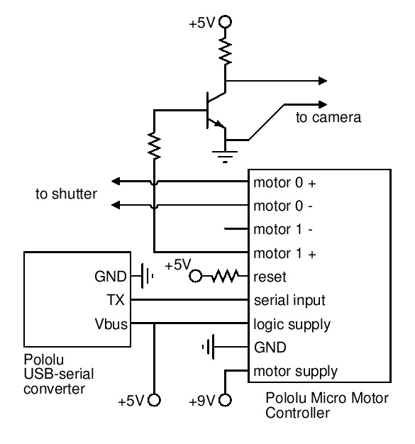
5 Minute Signal
For the past year and a half, a group based in Ann Arbor, Michigan, named GO-Tech has been formed, uniting individuals interested in creating projects using technology, such as hardware, software, metal, and wood. This initiative is referred to as...
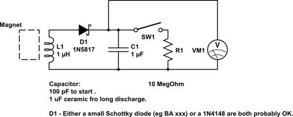
DIY kinetic energy harvester
A DIY kinetic energy harvester utilizing the electromagnetic method to generate electricity. The materials that will be used are currently known.
The project involves creating a kinetic energy harvester that converts mechanical energy from motion into electrical energy through electromagnetic induction....
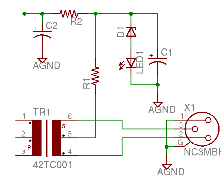
Help with a schematic please
A project is underway to construct the CountryHick DI as illustrated on DIYFactory, incorporating a few minor modifications. The final design aims to be a 1U unit with four inputs.
The CountryHick DI (Direct Injection) box is a crucial tool in...