


Levitation from 1996 Electronics Now Schematic
#levitation
#electromagnet
#AC/DC adapter
#voltage regulation
#12V power supply
#coil
#electronics project
#DIY
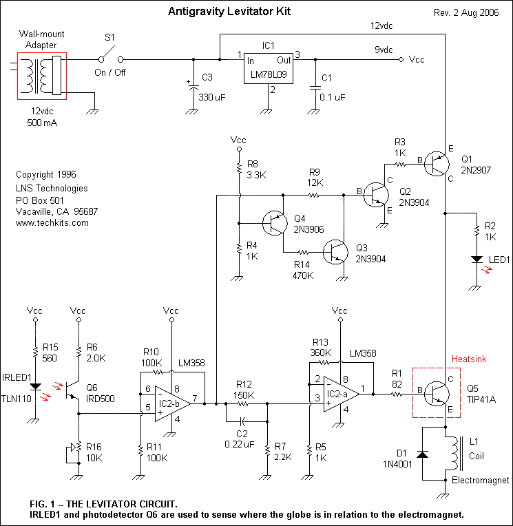
Description: This is the levitator's schematic. Power is supplied by a wall-mounted AC/DC adapter with an output of 12 volts DC at 500 milliamperes. The electromagnet coil draws most of the current in this circuit, so it is powered directly from the 12-volt output of the power adapter. Stable voltage for the rest of the circuit is obtained by regulating the adapter's output to 9 volts with IC1, an LM78L09 voltage regulator that is capable of supplying up to 100 milliamperes of current. Capacitors C1 and C3 provide additional voltage filtering. IRLED1 is an infrared light-emitting diode, similar to those used in infrared remote controls for consumer electronics. Resistor R2 limits the forward current to IRLED1 to about 15 milliamperes. The IRLED emits a constant, invisible beam whenever switch S1 is turned on. Phototransistor Q6 detects the infrared beam; it is wired with R6 and potentiometer R16 to convert the infrared beam into a DC voltage. Potentiometer R16 adjusts the output voltage of Q6, which is fed to pin 5 of IC2-b, one half of an LM358 operational amplifier. The op-amp, configured for a gain of two, buffers and amplifies the output of Q6. The output of IC2-b is fed to a second amplifier stage, IC2-a, through C2 and R12. The output signal from IC2-a drives transistor Q5 to vary the current to the electromagnet coil. Because Q5 gets very warm during operation, it requires a good heat sink. Diode D1 protects Q5 from reverse voltage spikes from the coil. Mylar capacitor C2 plays an important role in this circuit. It forms a differentiator with IC2-a. The capacitor blocks slow voltage changes but passes any rapid changes in the input signal, allowing them to be amplified by IC2-a. The slow voltage changes are attenuated by R12 and R7 before being amplified by IC2-a. The purpose of this part of the circuit is to perform closed-loop control using a combination of proportional and derivative modes. Both modes are needed to ensure that the levitation is stable. The rest of the circuit functions as a voltage-level detector that uses Q1 to switch the 12 volts to Q5 on or off. The level detector keeps the electromagnet powered off when there is no object in the beam to prevent overheating of the coil. The level detector also turns the electromagnet off if the object rises too far and completely blocks the beam. When nothing is blocking the infrared beam, the output of IC2-b will be greater than 2.7 volts. This causes Q4 and Q3 to turn on, which turns Q2 and Q1 off, so the electromagnet coil receives no current. Likewise, if the beam is completely blocked, the output of IC2-b will drop below 0.7 volts. Again, Q4 and Q3 will be on, which forces Q2 and Q1 off. However, when the object is partially blocking the beam during levitation, the voltage output from IC2-b should be somewhere between the 0.7 and 2.7-volt thresholds. In that case, Q4 and Q3 will be off, with Q2 and Q1 on. Whenever Q1 is on, the red LED indicates that Q5 and the coil are receiving current.
The circuit functions as a sophisticated levitation system, utilizing an AC/DC adapter to provide the necessary power. The primary voltage supply of 12 volts DC powers the electromagnet coil directly, which is essential for generating the magnetic field required for levitation. An LM78L09 voltage regulator is employed to step down the voltage to 9 volts for the remaining components, ensuring stable operation while providing adequate current capacity.
Capacitors C1 and C3 are integral to the circuit, serving as filters to smooth out any voltage fluctuations from the power supply. The IRLED1 emits an infrared beam, which is crucial for the levitation detection system. Resistor R2 is specifically selected to limit the current through IRLED1 to 15 milliamperes, ensuring optimal performance without exceeding the diode's specifications.
The phototransistor Q6 plays a pivotal role in detecting the infrared beam emitted by IRLED1. The output from Q6 is processed through a resistor R6 and a potentiometer R16, which allows for fine-tuning of the output voltage corresponding to the intensity of the detected infrared light. This voltage is then fed into the LM358 operational amplifier (IC2-b), where it is amplified to a usable level.
The second stage of amplification, IC2-a, receives the output from IC2-b and drives the control transistor Q5, which modulates the current supplied to the electromagnet coil based on the feedback from the levitation system. Given the thermal characteristics of Q5, a heat sink is necessary to dissipate heat generated during operation, preventing thermal runaway and ensuring reliable performance.
Diode D1 serves as a protective measure against voltage spikes that may occur when the electromagnet coil is de-energized, safeguarding the transistor Q5 from potential damage. The Mylar capacitor C2 is strategically used to form a differentiator circuit with IC2-a, allowing the system to respond rapidly to changes in the input signal while filtering out slower variations. This characteristic is essential for maintaining stability during levitation.
The level detection mechanism, utilizing transistor Q1, ensures that the electromagnet is powered down when no object is present within the infrared beam, thus preventing unnecessary energy consumption and overheating of the coil. The system is designed to respond dynamically to changes in the position of the levitating object, ensuring that it remains within a specified range. If the object moves too far away or completely blocks the beam, the circuit appropriately deactivates the electromagnet, maintaining safe operation. The visual indicator, a red LED, provides a clear indication of the operational status of the electromagnet coil, enhancing user awareness and system monitoring.This is the levitator`s schematic. Power is supplied by a wall mounted AC/DC adapter with an output of 12 volt DC at 500 milliamperes. The electromagnet coil draws most of the current in this circuit, so it is powered directly from the 12-volt output of the power adapter. Stable voltage for the rest of the circuit is obtained by regulating the adapter`s output to 9 volts with IC1, a LM78L09 voltage regulator that is capable of supplying up to 100 milliamperes of current. Capacitors C1 and C3 provide additional voltage filtering. IRLED1 is an infrared light emitting diode, much like those used in infrared remote controls for consumer-electronics equipment.
Resistor R2 limits the forward current to IRLED1 to about 15 milliamperes. The IRLED emits a constant, invisible beam whenever switch S1 is turned on. Phototransistor Q6 detects the infrared beam; it is wired with R6 and potentiometer R16 to convert the infrared beam into a DC voltage. Potentiometer R16 adjusts the output voltage of Q6, which is fed to pin 5 of IC2-b, one half of an LM358 operational amplifier.
The op-amp, which is configured for a gain of two, [(R11 + R10)/R11] buffer and amplifies the output of Q6. The output of IC2-b is fed to a second amplifier stage, IC2-a through C2 and R12. The output signal from IC2-a drives transistor Q5 to vary the current to the electromagnet coil. Because Q5 gets very warm during operation, it requires a good heat sink. Diode D1 protects Q5 from reverse voltage spikes from the coil. Mylar capacitor C2 plays an important role in this circuit. It forms a differentiator with IC2-a. The capacitor blocks slow voltage changes, but passes any rapid changes in the input signal and allows them to be amplified by IC2-a.
The slow voltage changes are attenuated by R12 and R7 before being amplified by IC2-a. The purpose of this part of the circuit is to perform closed-loop control using a combination of proportional and derivative modes. Both modes are needed to insure that the levitation is stable. Ther est of the circuit functions as a voltage-level detector that uses Q1 to switch the 12-volts to Q5 on or off.
The level detector keeps the electromagnet powered off when there is no object in the beam. This is to prevent overheating of the coil. The level detector also turns the electromagnet off if the object rises too far and completely blocks the beam. When nothing is blocking the infrared beam, the output of IC2-b will be greater than 2. 7 volts. This causes Q4 and Q3 to turn on, which turns Q2 and Q1 off, so the electromagnet coil receives no current.
Likewise, if the beam is completely blocked, the output of IC2-b will drop below 0. 7-volts. Again Q4 and Q3 will be on which forces Q2 and Q1 off. However, when the object is partially blocking the beam during levitation, the voltage out of IC2-b should be somewhere between the 0. 7 and 2. 7-volt thresholds. In that case, Q4 and Q3 will be off, with Q2 and Q1 on. Whenever Q1 is on, the red LED indicates that Q5 and the coil are receiving current.
The circuit functions as a sophisticated levitation system, utilizing an AC/DC adapter to provide the necessary power. The primary voltage supply of 12 volts DC powers the electromagnet coil directly, which is essential for generating the magnetic field required for levitation. An LM78L09 voltage regulator is employed to step down the voltage to 9 volts for the remaining components, ensuring stable operation while providing adequate current capacity.
Capacitors C1 and C3 are integral to the circuit, serving as filters to smooth out any voltage fluctuations from the power supply. The IRLED1 emits an infrared beam, which is crucial for the levitation detection system. Resistor R2 is specifically selected to limit the current through IRLED1 to 15 milliamperes, ensuring optimal performance without exceeding the diode's specifications.
The phototransistor Q6 plays a pivotal role in detecting the infrared beam emitted by IRLED1. The output from Q6 is processed through a resistor R6 and a potentiometer R16, which allows for fine-tuning of the output voltage corresponding to the intensity of the detected infrared light. This voltage is then fed into the LM358 operational amplifier (IC2-b), where it is amplified to a usable level.
The second stage of amplification, IC2-a, receives the output from IC2-b and drives the control transistor Q5, which modulates the current supplied to the electromagnet coil based on the feedback from the levitation system. Given the thermal characteristics of Q5, a heat sink is necessary to dissipate heat generated during operation, preventing thermal runaway and ensuring reliable performance.
Diode D1 serves as a protective measure against voltage spikes that may occur when the electromagnet coil is de-energized, safeguarding the transistor Q5 from potential damage. The Mylar capacitor C2 is strategically used to form a differentiator circuit with IC2-a, allowing the system to respond rapidly to changes in the input signal while filtering out slower variations. This characteristic is essential for maintaining stability during levitation.
The level detection mechanism, utilizing transistor Q1, ensures that the electromagnet is powered down when no object is present within the infrared beam, thus preventing unnecessary energy consumption and overheating of the coil. The system is designed to respond dynamically to changes in the position of the levitating object, ensuring that it remains within a specified range. If the object moves too far away or completely blocks the beam, the circuit appropriately deactivates the electromagnet, maintaining safe operation. The visual indicator, a red LED, provides a clear indication of the operational status of the electromagnet coil, enhancing user awareness and system monitoring.This is the levitator`s schematic. Power is supplied by a wall mounted AC/DC adapter with an output of 12 volt DC at 500 milliamperes. The electromagnet coil draws most of the current in this circuit, so it is powered directly from the 12-volt output of the power adapter. Stable voltage for the rest of the circuit is obtained by regulating the adapter`s output to 9 volts with IC1, a LM78L09 voltage regulator that is capable of supplying up to 100 milliamperes of current. Capacitors C1 and C3 provide additional voltage filtering. IRLED1 is an infrared light emitting diode, much like those used in infrared remote controls for consumer-electronics equipment.
Resistor R2 limits the forward current to IRLED1 to about 15 milliamperes. The IRLED emits a constant, invisible beam whenever switch S1 is turned on. Phototransistor Q6 detects the infrared beam; it is wired with R6 and potentiometer R16 to convert the infrared beam into a DC voltage. Potentiometer R16 adjusts the output voltage of Q6, which is fed to pin 5 of IC2-b, one half of an LM358 operational amplifier.
The op-amp, which is configured for a gain of two, [(R11 + R10)/R11] buffer and amplifies the output of Q6. The output of IC2-b is fed to a second amplifier stage, IC2-a through C2 and R12. The output signal from IC2-a drives transistor Q5 to vary the current to the electromagnet coil. Because Q5 gets very warm during operation, it requires a good heat sink. Diode D1 protects Q5 from reverse voltage spikes from the coil. Mylar capacitor C2 plays an important role in this circuit. It forms a differentiator with IC2-a. The capacitor blocks slow voltage changes, but passes any rapid changes in the input signal and allows them to be amplified by IC2-a.
The slow voltage changes are attenuated by R12 and R7 before being amplified by IC2-a. The purpose of this part of the circuit is to perform closed-loop control using a combination of proportional and derivative modes. Both modes are needed to insure that the levitation is stable. Ther est of the circuit functions as a voltage-level detector that uses Q1 to switch the 12-volts to Q5 on or off.
The level detector keeps the electromagnet powered off when there is no object in the beam. This is to prevent overheating of the coil. The level detector also turns the electromagnet off if the object rises too far and completely blocks the beam. When nothing is blocking the infrared beam, the output of IC2-b will be greater than 2. 7 volts. This causes Q4 and Q3 to turn on, which turns Q2 and Q1 off, so the electromagnet coil receives no current.
Likewise, if the beam is completely blocked, the output of IC2-b will drop below 0. 7-volts. Again Q4 and Q3 will be on which forces Q2 and Q1 off. However, when the object is partially blocking the beam during levitation, the voltage out of IC2-b should be somewhere between the 0. 7 and 2. 7-volt thresholds. In that case, Q4 and Q3 will be off, with Q2 and Q1 on. Whenever Q1 is on, the red LED indicates that Q5 and the coil are receiving current.
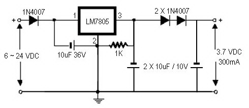
how to convert a 9v battery to 3.7v
A regulator circuit is needed for this DIY project. Familiarity with electronic components, circuitry, the use of a multitester, and a soldering iron is essential. The schematic diagram provided can accept an input voltage ranging from 6 to 24 volts...
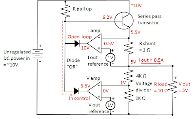
how does power supply regulate its
Most power supplies regulate either their output voltage or current at a constant level, depending on the load resistance relative to the power supply's output voltage and current settings. This can be summarized as follows: To accomplish this, most power...
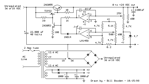
variable voltage and current power supply
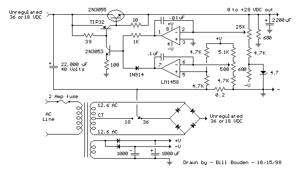
An alternative method for utilizing operational amplifiers (op-amps) to regulate a power supply is illustrated below. The power transformer necessitates an additional winding to provide the op-amps with a bipolar voltage of +/- 8 volts. This negative voltage is also...
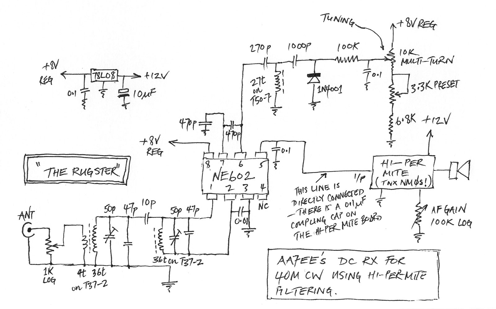
MePADS
If you are considering building the Desert Ratt 2, it is advisable to read all the accompanying text, as it contains relevant construction details. Engaging with the comments and replies can also provide additional insights, as previous blog posts have...
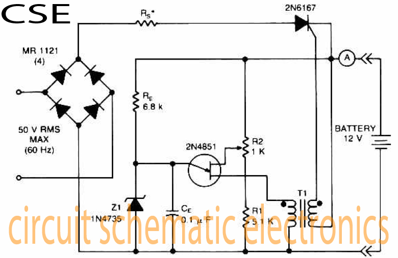
Variable charger circuit Schematic Diagram
The accumulator charger circuit must provide a voltage that matches the specifications of the batteries being charged. For a 12-volt accumulator, the output voltage should not exceed 12 volts, nor should it fall significantly below this threshold. Failure to maintain...
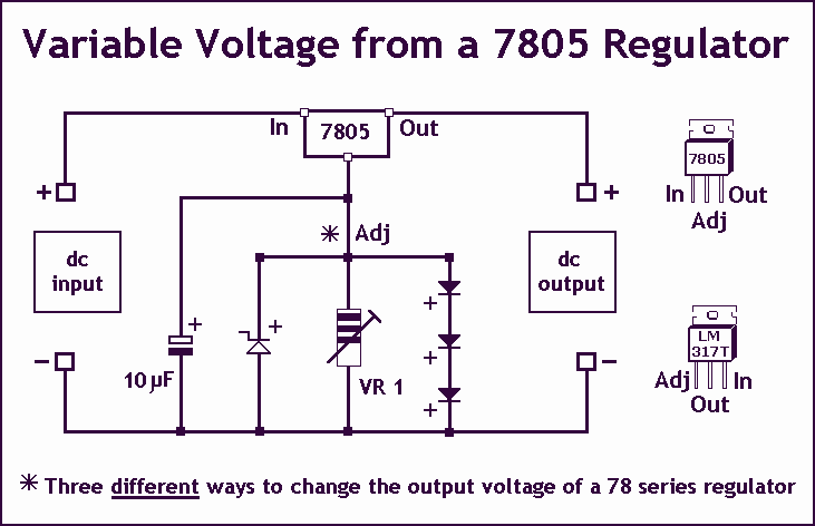
Variable Voltage Regulation
Controlling the output voltage from a regulator can be made variable in three ways:
1. Using a fixed reference zener diode to increase the output by the value of the zener
2. A variable resistor for variable output, note that...
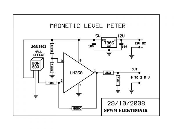
STEORN DEMO LIVE & STREAM
The positioning of a coil by even a millimeter can significantly impact the success or failure of a project. When there are tens of millimeters of possible positions, the likelihood of incorrect placement—and thus failure—greatly increases. This situation necessitates an...
Current and Variable Voltage Power Supply
Another adjustment of application operational amplifiers to adapt a power supply is apparent below. The power supply requires an additional adjustment to supply the op-amps with a bipolar voltage (+/- 8 volts), and the negative voltage is also used to...
Homemade Metal Detector Kit
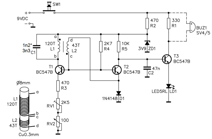
A simple home project can quickly become problematic if it encounters electric cables, gas, or water pipes, or the central heating system. Using a metal detector allows one to check for metal objects within walls, ceilings, or floors beforehand. An...