


LOTTO NUMBER SELECTOR
#lotto
#selector
#gambling
#manual mode
#automatic mode
#random number
#game
#entertainment
#electronics project
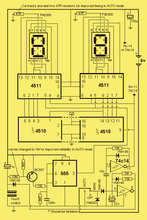
Description: This project is a real winner in more ways than one. When you understand how the circuit works, it is really 4 projects in one. And it has two modes of operation: MANUAL and AUTOMATIC. Everyone likes a little flutter. The introduction of so many outlets in competition for the gambling dollar is positive proof of this. Every week the total prize pool for these games rises and this alone must draw in many new customers. More: Our circuit is a real gem. It looks simple but lurking within the 5 chips are a number of interesting building blocks. The most significant feature of the circuit is the absence of 14 display resistors. Both the 4511's are display drivers and under
The described circuit is a multifaceted project that operates in two distinct modes: Manual and Automatic. The design effectively utilizes five integrated circuits (ICs), which serve various functions, creating a versatile platform capable of supporting multiple applications. The dual-mode capability allows users to interact with the circuit in a hands-on manner or allow it to function autonomously, catering to different user preferences.
The absence of 14 display resistors is a noteworthy feature of this circuit. Typically, display drivers require several resistors to limit current and protect the display elements. In this design, both of the 4511 ICs function as display drivers, which simplifies the circuit layout and reduces component count. This not only enhances reliability but also minimizes the potential for failure, as fewer components are involved.
The 4511 ICs are BCD to 7-segment latch decoders/drivers that efficiently convert binary-coded decimal inputs into the corresponding 7-segment display outputs. This capability is essential for visual representation of numerical data, which is crucial in applications such as gaming or scorekeeping. The circuit likely incorporates additional logic elements to manage the switching between manual and automatic modes, possibly utilizing flip-flops or multiplexers to facilitate user input and automated functions.
Furthermore, the project is designed with a focus on user engagement, as indicated by its connection to gambling and prize pools. The circuit may include features that track scores, manage payouts, or display odds, making it not only functional but also appealing in a competitive environment. Overall, this project represents a sophisticated integration of digital logic and user interface design, showcasing the potential for innovative applications in electronic gaming and beyond.This project is a real winner in more ways than one. When you understand how the circuit works, it is really 4 projects in one. And it has two modes of operation: MANUAL and AUTOMATIC. Everyone likes a little flutter. The introduction of so many outlets in competition for the gambling dollar is positive proof of this. Every week the total prize pool for these games rises and this alone must draw in many new customers.
Our circuit is a real gem. It looks simple but lurking within the 5 chips are a number of interesting building blocks. The most significant feature of the circuit is the absence of 14 display resistors. Both the 4511`s are display drivers and under
The described circuit is a multifaceted project that operates in two distinct modes: Manual and Automatic. The design effectively utilizes five integrated circuits (ICs), which serve various functions, creating a versatile platform capable of supporting multiple applications. The dual-mode capability allows users to interact with the circuit in a hands-on manner or allow it to function autonomously, catering to different user preferences.
The absence of 14 display resistors is a noteworthy feature of this circuit. Typically, display drivers require several resistors to limit current and protect the display elements. In this design, both of the 4511 ICs function as display drivers, which simplifies the circuit layout and reduces component count. This not only enhances reliability but also minimizes the potential for failure, as fewer components are involved.
The 4511 ICs are BCD to 7-segment latch decoders/drivers that efficiently convert binary-coded decimal inputs into the corresponding 7-segment display outputs. This capability is essential for visual representation of numerical data, which is crucial in applications such as gaming or scorekeeping. The circuit likely incorporates additional logic elements to manage the switching between manual and automatic modes, possibly utilizing flip-flops or multiplexers to facilitate user input and automated functions.
Furthermore, the project is designed with a focus on user engagement, as indicated by its connection to gambling and prize pools. The circuit may include features that track scores, manage payouts, or display odds, making it not only functional but also appealing in a competitive environment. Overall, this project represents a sophisticated integration of digital logic and user interface design, showcasing the potential for innovative applications in electronic gaming and beyond.This project is a real winner in more ways than one. When you understand how the circuit works, it is really 4 projects in one. And it has two modes of operation: MANUAL and AUTOMATIC. Everyone likes a little flutter. The introduction of so many outlets in competition for the gambling dollar is positive proof of this. Every week the total prize pool for these games rises and this alone must draw in many new customers.
Our circuit is a real gem. It looks simple but lurking within the 5 chips are a number of interesting building blocks. The most significant feature of the circuit is the absence of 14 display resistors. Both the 4511`s are display drivers and under
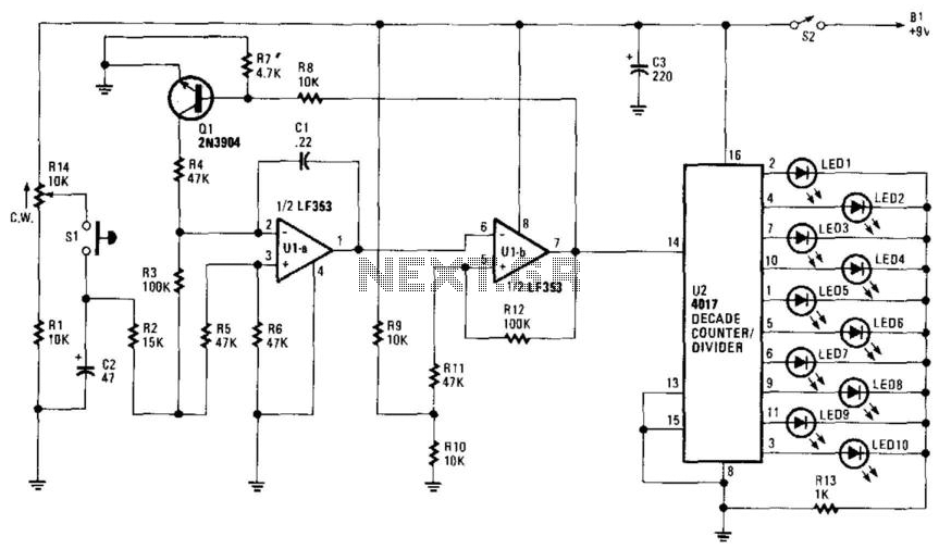
Electronic Roulette Game
R14 is configured to establish an initial "starting" speed for the oscillators U1A and U1B. As capacitor C2 charges, the oscillation gradually slows down during the discharging phase of C2, creating a roulette-wheel effect on LED S1 through resistor R10....
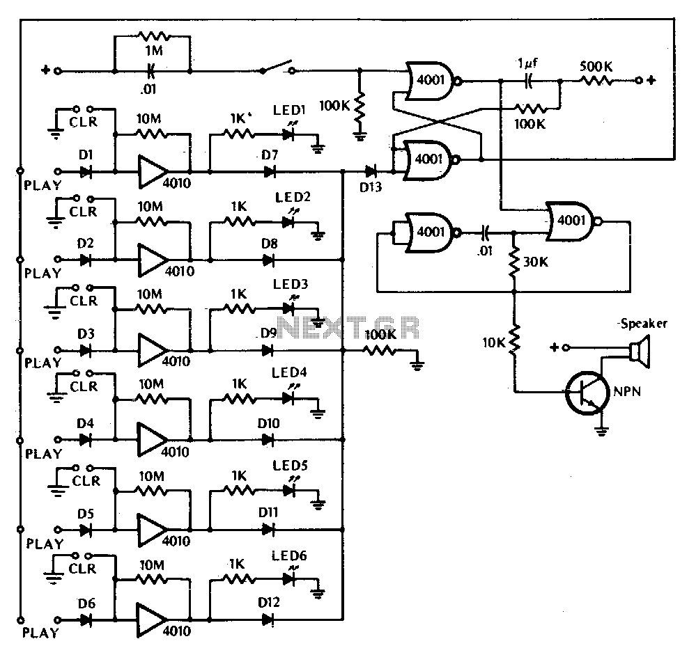
Ready set goi
This game tests a player's reaction time. It is activated by closing switch SI, which starts the tone generator and arms the circuit. The touchplate, labeled PLAY in the diagram, consists of two metal strips about 1/16th inch apart. The...
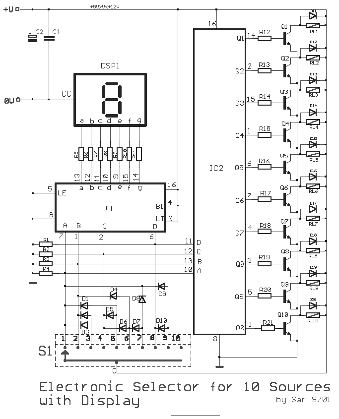
Electronic Selector for 10 sources with Display-Relay Drive circuit
This circuit is designed for the selection of alternative sources. It integrates mechanical selection through a rotating switch S1, electronic control of relays RL1 to RL10, and optical indication of the selection via the display DSP1.
The circuit operates by allowing...
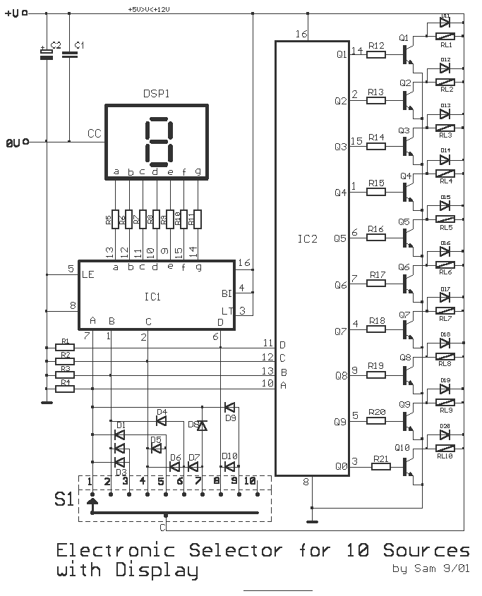
Electronic 10 way Selector Relays
This is a circuit for alternative sources selection. It combines mechanical selection using a rotating switch S1, the electronic drive of the relays RL 1-10 and also the optical indication of the selection by the Display DSP1. The function is...
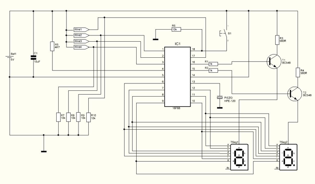
Bomb Deactivation Game
Should I cut the blue wire... or the red...? This is a very common phrase in many movies when the action hero has a bomb in front of him with little time left and he has to choose which wire...
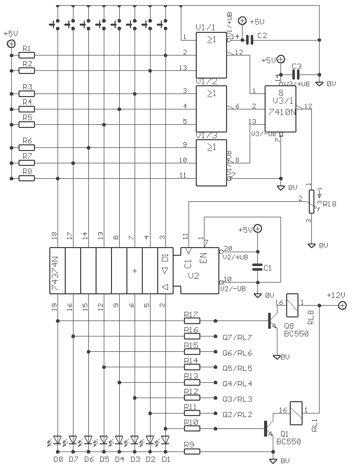
8 way electronic selector / switch
The Elect. Sel. 8 is a simple circuit, with a choice of 8 sources of any sort, of 8 independent switches. Each switch corresponding with a relay for example the switch S1 activates the RL1 etc. The uses of the...
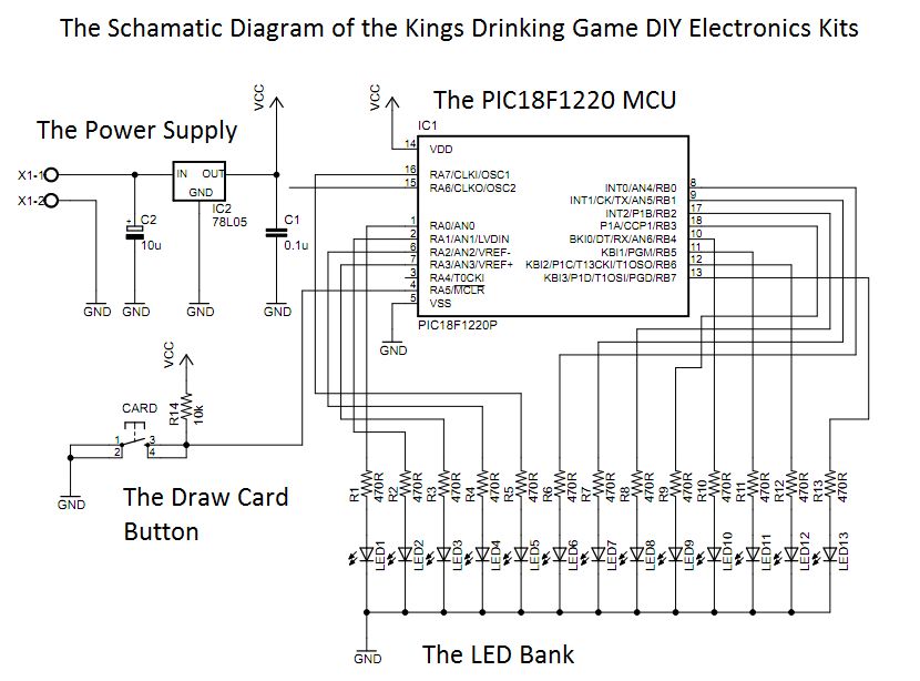
The Electronic Kings drinking game circuit!
This circuit was designed approximately four months ago and has been developed into a kit for others to use.
The circuit in question appears to be a well-thought-out design that has been packaged into a kit format, making it accessible for...
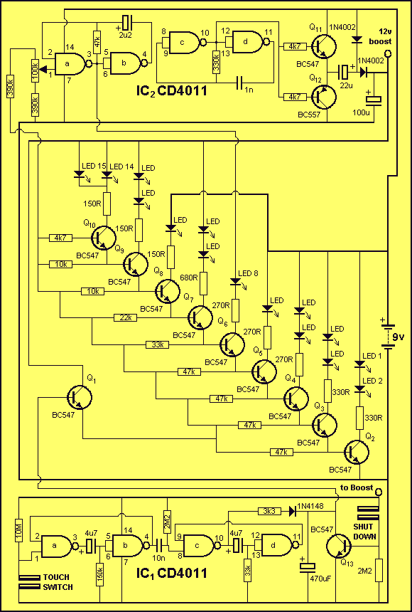
HANGMAN schematic
Everybody likes re-discovering something they did years ago. Here's a game we all played at school. Possibly under the name of HANG THE BUTCHER. The game is quite simple. One player thinks of a word and writes down the number...
Bomb Deactivation Game
Should I cut the blue wire... or the red...? This is a very common phrase in many movies when the action hero has a bomb in front of him with little time left and he has to choose which wire...