


Mechanical TV System
#mechanical TV
#color filters
#phototransistors
#photodiodes
#matrix circuit
#inverter
#additive primary colors
#complementary colors
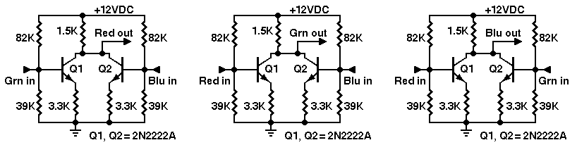
Description: Construct a two-color camera and a three-color monitor. The camera can be designed to capture any two of the additive primary colors by placing the appropriate color filters over phototransistors or photodiodes. A matrix circuit and an inverter will be used to derive the third color. Although the third color may not be directly captured, its complement can be created. A bit of electronics can convert the complement back into the "missing" primary color. At the monitor, connect a potentiometer to the red and green LED driver outputs. This potentiometer acts as a resistor matrix. A specific point on the potentiometer's resistance element corresponds to yellow, which is the complement of blue. The red signal is located at one end of the potentiometer, while the blue signal is at the opposite end. When the wiper is positioned at the center, a mixture of red and blue is obtained, resulting in magenta. This magenta signal is desired. By centering the wiper and connecting it to the base of a new transistor (or an op-amp input), the magenta signal can be inverted. The inverted signal serves as the green drive signal. To derive the red signal, the green and blue signals are utilized. Cyan, positioned between green and blue, can be inverted using a transistor to produce the red signal. An inverting mixer is an effective approach to derive this third color. For experimental purposes, the circuits can be used as they are, although the phasing may only be approximate. To improve phasing, level-adjustment pots can be added to the transistor inputs. Each transistor functions as an inverting phase-splitter, providing a 180-degree phase shift while mixing input signals at the common collector resistor. Despite having no voltage gain, each amplifier offers an 11.8-times power gain. The in-phase signal can be taken from the emitter of each transistor, which includes the power gain. The pseudocolor (P/C) technique does not require modifications to the camera or video source. Instead, it is an automatic process that interpolates color from a monochrome source, resulting in output colors that may not appear naturalistic but can be useful in various applications. While most modern pseudocolor systems are digital, effective analog systems also exist and can operate in real-time. Pseudocolors can be derived from monochrome signals using various methods. The most advanced systems utilize digital quantization of gray levels, where a computer assigns colors to medium levels while peak levels remain black and white. The simplest pseudocolor system outputs two colors without requiring quantization or digital circuits. A two-ended analog amplifier is suitable for this purpose. Effective pseudocolors can be achieved by applying the monochrome signal to the inputs of a difference amplifier. The inverted signal drives one color output while the non-inverted signal drives the other. In the provided schematic, the collector of transistor Q1 outputs the inverted or orange signal, while the non-inverted cyan signal appears on the collector of transistor Q2. These two collector signals are 180 degrees out of phase. The output resistors can be fixed or variable, and using variable resistors allows for white balance adjustments. When the output appears white, balance is achieved. A third color can be derived as the midrange or difference signal between the two output signals, such as the midpoint of a 50K potentiometer connecting Q1 and Q2 collectors. This third signal is 90 degrees out of phase with each of the other two signals. If the potentiometer is smaller than 33K, it may introduce crosstalk between the Q1 and Q2 outputs, altering the phase relationship among the three signals, similar to the operation of a color TV matrix.
The two-color camera operates by integrating phototransistors or photodiodes equipped with specific color filters that correspond to the additive primary colors—red, green, and blue. This selection allows the camera to capture two colors simultaneously. The matrix circuit plays a crucial role in processing the signals from the camera, enabling the generation of the third color through the use of an inverter. The inverter's output is crucial for creating the complementary color, which is then manipulated further within the system.
The monitor circuitry involves a potentiometer that serves as a variable resistor matrix, allowing for fine-tuning of the output signals. By adjusting the potentiometer, specific color outputs can be achieved, including yellow as the complement of blue. The operational flow from the potentiometer through the transistor or op-amp ensures that the desired colors are generated accurately, with the wiper position determining the resultant color mix.
The inverting mixer configuration is essential for deriving the red signal from the green and blue inputs. This setup allows for the necessary phase shifts and signal mixing that are required to achieve accurate color representation. Each transistor in the circuit acts as a phase-splitter, ensuring that the output maintains the required phase relationships for effective color mixing.
Pseudocolor techniques add versatility to the system, allowing for the interpolation of colors from monochrome sources. This can be particularly useful in applications where color fidelity is not critical, and the focus is on enhancing visual data representation. The implementation of analog systems that operate in real-time, alongside the digital counterparts, provides a robust framework for various applications in imaging and color processing.
Overall, the described system exemplifies a sophisticated approach to color imaging, utilizing both fundamental electronic principles and advanced techniques to achieve the desired outcomes in color representation.Build a two-color camera and a three-color monitor. You can build your camera to pick up any two of the additive primary colors. Just install the proper color filters over the phototransistors or photodiodes. With a matrix circuit and an inverter, you will derive the third color. The trick You might not have thethird color, but you can create its complement. A bit of electronics turns the complement back into the "missing" primary color. At the monitor, connect a potentiometer to the red and green LED driver outputs. This potentiometer is your resistor matrix. Some point on the pot`s resistance element corresponds to yellow, the complement of blue. The red signal is at one end of the potentiometer. The blue signal is at the other end. With the wiper at the center position, you get a mix of red and blue, or magenta. This magenta signal is what you want. Center the wiper. Run the wiper of the pot to the base of a new transistor (or an op amp input). With the transistor or op amp, invert the magenta signal. The inverted signal is your green drive signal. Derive Red. Now you want red, but only have green and blue. Cyan is between green and blue. With a transistor, invert the cyan signal and you have your red. Inverting mixer. An inverting mixer is an easy way to derive a third color. (See the schematics above. ) For experimental use, use the circuits as-is. The phasing is only approximate. For better phasing, add level-adjustment pots to the transistor inputs. Theory. Each transistor is an inverting phase-splitter. After a 180-degree phase shift, the input signals mix at the common collector resistor. Neither amplifier has any voltage gain. Yet each amplifier offers an 11. 8-times power gain. You can take the in-phase signal off the emitter of each transistor. The emitter signal includes the power gain. No camera. Pseudocolor (P/C) requires no modifications to the camera or video source. Instead, pseudocolor is an automatic process that interpolates color from a monochrome source. The output color will likely not be naturalistic, but it might be useful in some applications. Although most contemporary pseudocolor systems are digital, very acceptable analog systems exist. Either type system can work in real time. Quantizing. You can derive pseudocolors from monochrome in many ways. The most sophisticated systems rely on digital quantizing of gray levels. A computer assigns a color to at least the medium levels. Typically, the peak levels remain black and white. The simplest pseudocolor system outputs two colors. This method requires no quantizing and no digital circuits. A two-ended analog amplifier will serve excellently. You can achieve very effective pseudocolors by applying the monochrome signal to the inputs of a difference amplifier. The inverted signal then drives one color output. The non-inverted signal drives the other color output. In the nearby schematic, the collector of transistor Q1 provides the inverted or orange signal. The cyan, non-inverted signal appears on the collector of transistor Q2. The two collector signals are 180 degrees out of phase with one another. The output resistors may be fixed or variable. Using variable resistors and a maximum signal, you can adjust the white balance. When the output appears white, you`ve achieved balance. If you desire a third color, it could be the midrange or difference signal between the two output signals.
(For example, the midpoint of a 50K pot VRZ that connects between the Q1 and Q2 collectors. ) The third signal is 90 degrees out of phase with each of the other two signals. If VRZ is smaller than 33K, it introduces crosstalk between the Q1 and Q2 outputs. The crosstalk alters the phase relationship of the three signals. (This is how a matrix in a color TV works. )
The two-color camera operates by integrating phototransistors or photodiodes equipped with specific color filters that correspond to the additive primary colors—red, green, and blue. This selection allows the camera to capture two colors simultaneously. The matrix circuit plays a crucial role in processing the signals from the camera, enabling the generation of the third color through the use of an inverter. The inverter's output is crucial for creating the complementary color, which is then manipulated further within the system.
The monitor circuitry involves a potentiometer that serves as a variable resistor matrix, allowing for fine-tuning of the output signals. By adjusting the potentiometer, specific color outputs can be achieved, including yellow as the complement of blue. The operational flow from the potentiometer through the transistor or op-amp ensures that the desired colors are generated accurately, with the wiper position determining the resultant color mix.
The inverting mixer configuration is essential for deriving the red signal from the green and blue inputs. This setup allows for the necessary phase shifts and signal mixing that are required to achieve accurate color representation. Each transistor in the circuit acts as a phase-splitter, ensuring that the output maintains the required phase relationships for effective color mixing.
Pseudocolor techniques add versatility to the system, allowing for the interpolation of colors from monochrome sources. This can be particularly useful in applications where color fidelity is not critical, and the focus is on enhancing visual data representation. The implementation of analog systems that operate in real-time, alongside the digital counterparts, provides a robust framework for various applications in imaging and color processing.
Overall, the described system exemplifies a sophisticated approach to color imaging, utilizing both fundamental electronic principles and advanced techniques to achieve the desired outcomes in color representation.Build a two-color camera and a three-color monitor. You can build your camera to pick up any two of the additive primary colors. Just install the proper color filters over the phototransistors or photodiodes. With a matrix circuit and an inverter, you will derive the third color. The trick You might not have thethird color, but you can create its complement. A bit of electronics turns the complement back into the "missing" primary color. At the monitor, connect a potentiometer to the red and green LED driver outputs. This potentiometer is your resistor matrix. Some point on the pot`s resistance element corresponds to yellow, the complement of blue. The red signal is at one end of the potentiometer. The blue signal is at the other end. With the wiper at the center position, you get a mix of red and blue, or magenta. This magenta signal is what you want. Center the wiper. Run the wiper of the pot to the base of a new transistor (or an op amp input). With the transistor or op amp, invert the magenta signal. The inverted signal is your green drive signal. Derive Red. Now you want red, but only have green and blue. Cyan is between green and blue. With a transistor, invert the cyan signal and you have your red. Inverting mixer. An inverting mixer is an easy way to derive a third color. (See the schematics above. ) For experimental use, use the circuits as-is. The phasing is only approximate. For better phasing, add level-adjustment pots to the transistor inputs. Theory. Each transistor is an inverting phase-splitter. After a 180-degree phase shift, the input signals mix at the common collector resistor. Neither amplifier has any voltage gain. Yet each amplifier offers an 11. 8-times power gain. You can take the in-phase signal off the emitter of each transistor. The emitter signal includes the power gain. No camera. Pseudocolor (P/C) requires no modifications to the camera or video source. Instead, pseudocolor is an automatic process that interpolates color from a monochrome source. The output color will likely not be naturalistic, but it might be useful in some applications. Although most contemporary pseudocolor systems are digital, very acceptable analog systems exist. Either type system can work in real time. Quantizing. You can derive pseudocolors from monochrome in many ways. The most sophisticated systems rely on digital quantizing of gray levels. A computer assigns a color to at least the medium levels. Typically, the peak levels remain black and white. The simplest pseudocolor system outputs two colors. This method requires no quantizing and no digital circuits. A two-ended analog amplifier will serve excellently. You can achieve very effective pseudocolors by applying the monochrome signal to the inputs of a difference amplifier. The inverted signal then drives one color output. The non-inverted signal drives the other color output. In the nearby schematic, the collector of transistor Q1 provides the inverted or orange signal. The cyan, non-inverted signal appears on the collector of transistor Q2. The two collector signals are 180 degrees out of phase with one another. The output resistors may be fixed or variable. Using variable resistors and a maximum signal, you can adjust the white balance. When the output appears white, you`ve achieved balance. If you desire a third color, it could be the midrange or difference signal between the two output signals.
(For example, the midpoint of a 50K pot VRZ that connects between the Q1 and Q2 collectors. ) The third signal is 90 degrees out of phase with each of the other two signals. If VRZ is smaller than 33K, it introduces crosstalk between the Q1 and Q2 outputs. The crosstalk alters the phase relationship of the three signals. (This is how a matrix in a color TV works. )
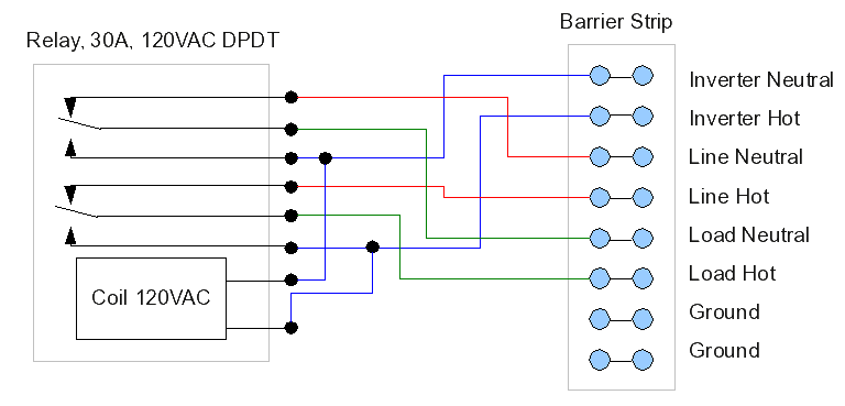
Inverter/Charger relay
After experiencing equipment failure, a decision was made to replace a combination inverter/charger unit with individual components that fulfill the same requirements. The combination unit, referred to as the "Everything Box," is an efficient solution for cost savings by integrating...
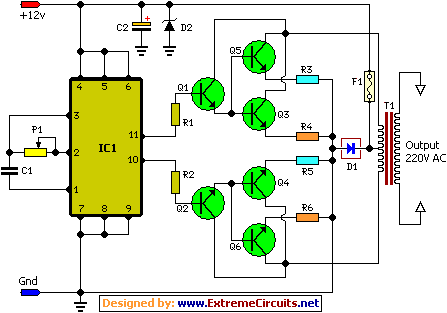
100w inverter circuit schematic
This document describes a 100 Watt inverter circuit that utilizes a minimal number of components. The circuit employs the CD 4047 integrated circuit (IC) from Texas Instruments to generate 100 Hz pulses, along with four 2N3055 transistors that drive the...
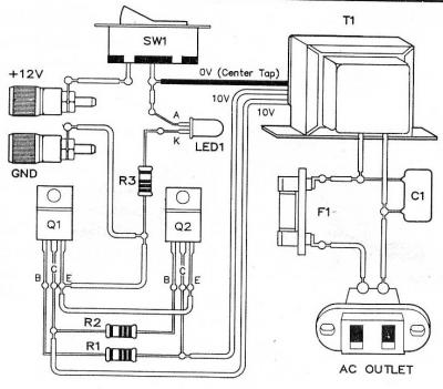
Micro Inverter by 2N6121
This is a micro inverter, which is a small-sized inverter that modifies energy from a small-sized battery, providing an output voltage of approximately 220V AC.
Micro inverters are compact devices designed to convert direct current (DC) electricity from solar panels or...
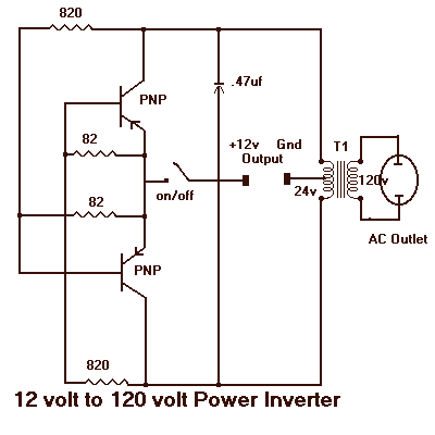
12 to 120 Volt Inverter
It will supply 15 watts of AC power to a device. It should power lamps, shavers, small stereos and small appliances. If you draw too much power the circuit will shut down all by itself. The output of this circuit...
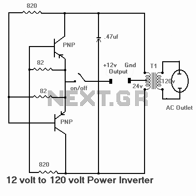
inverter circuits
Some good inverter circuits I found oscillate at approximately 50 to 60 Hz. They are likely capable of handling up to two amps; any more than that will cause them to automatically shut off. If there are questions, please leave...
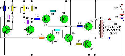
Small wattage Inverter (Inverter Circuit For Soldering Iron)
This is a simple and cost-effective inverter designed for small soldering irons (25W, 35W, etc.) to be used in the absence of mains supply. The circuit employs eight transistors along with a few resistors and capacitors. Transistors Q1 and Q2...
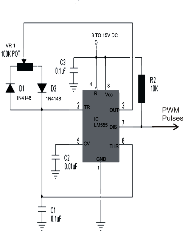
Make This 1KVA (1000 watts) Pure Sine Wave Inverter Circuit
The configuration presented in the diagram below is a simple MOSFET-based design intended for amplifying current at ±60 volts, allowing the connected transformer to generate a required output of 1 kVA. The components Q1 and Q2 form the initial differential...
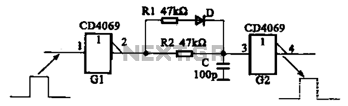
And broadening the delay circuit
The inverter circuit using CD4069 is configured with a delay and width adjustment. When the output of the inverter (G1) is high, the capacitor (C) charges through resistor (R1) and diode (D). The voltage across capacitor C quickly reaches the...
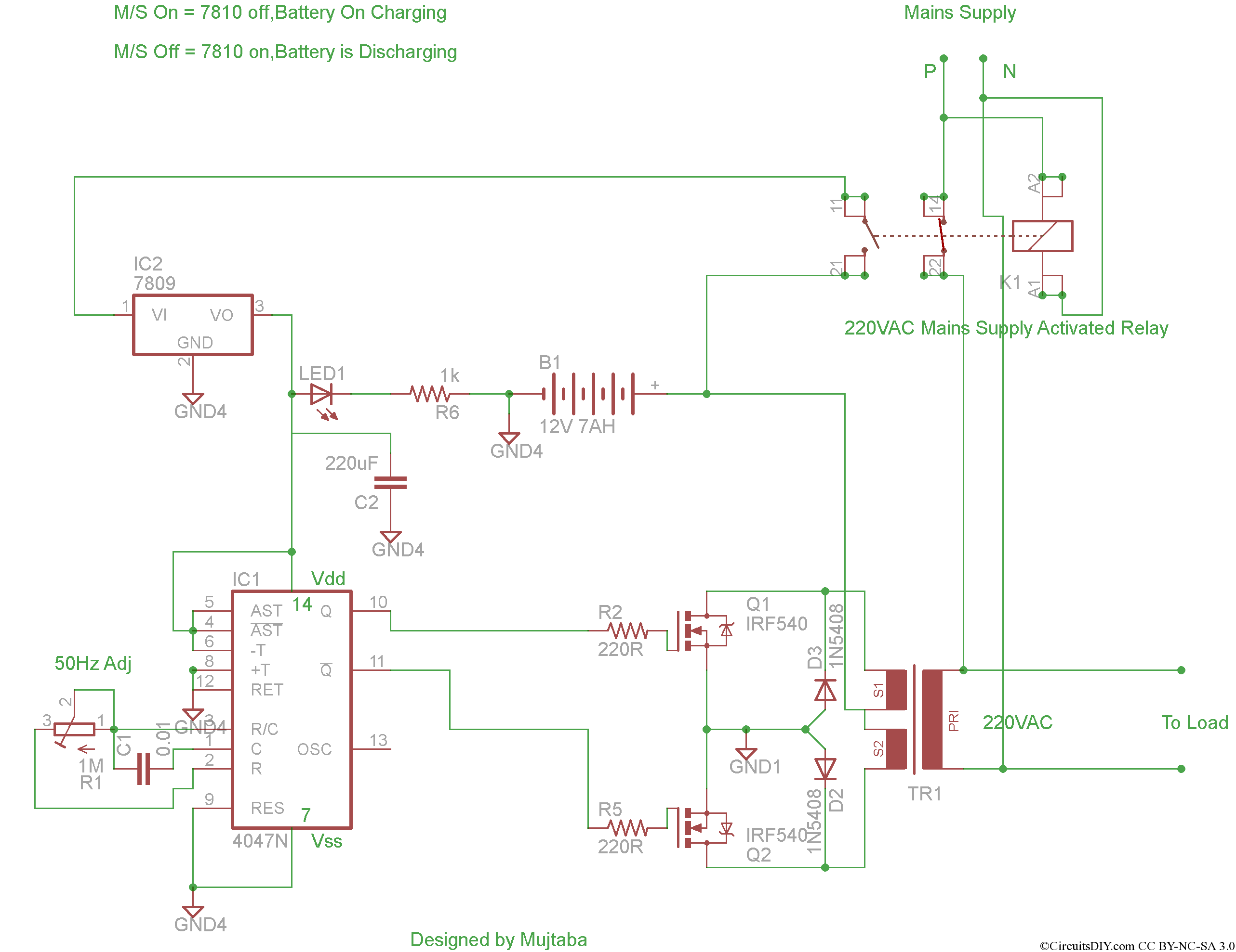
A complete Inverter project
This project involves the development of a complete inverter system that features automatic mains switching, automatic charging when mains power is available, and automatic inverter activation when mains power is lost. The goal is to build a solar inverter capable...