


Mini efficient coil launcher from disposable camera flash
#coil launcher
#disposable camera
#ferromagnetic
#projectile
#pulse power
#DIY
#electronics
#fun project
#magnetic
#hobby
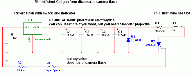
Description: This project is a fun and safe activity for individuals interested in magnetically launching projectiles. The operation involves placing a ferromagnetic projectile at one end of a coil and applying a power pulse. The key is to turn off the power when the projectile reaches the midpoint of the coil. There are various methods to achieve this, but they are not the focus here. Another important technique is to position the coil as close as possible to the projectile to maximize coupling, while also avoiding saturation by keeping the current at a manageable level. Initial experiments involved a basic model using a straw wrapped with wire and a 200V electrolytic capacitor, which successfully launched a nail across a room. Subsequent experiments included wrapping wire around glass and using larger electrolytics charged by mains power, which proved bulky and less effective. Following a break, more advanced experiments were conducted using SCRs (silicon-controlled rectifiers), photoflash electrolytics, and optical sensors, resulting in a bi-coil launcher that was powerful but required precise timing, necessitating transient simulations and an L-C-R meter. Future designs include a MOSFET-switched launcher with three coils and optical sensors, although funding and parts are currently limited. A small coil launcher is being constructed using one SCR and a coil on glass, designed for maximum efficiency with the aid of an LCR meter and Multisim simulator. For this project, four disposable camera flashes are needed. The capacitors, rated at 330V and 120-160μF, can handle pulses up to 300A. Paralleling them reduces equivalent series resistance (ESR) and increases peak current capability. The current setup achieves a pulse current of 400A, with a recommendation to limit the number of capacitors to four for optimal performance. The charging circuit should utilize the largest components available, and more batteries can be used for faster charging. The capacitors are mounted on a breadboard with parallel solder tracks to prevent failure. The coil consists of 200 turns of 1mm diameter insulated magnet wire, wound on a glass pipe. The resistance and inductance measurements indicate a pulse length of 1 ms with a peak current limited by inductance. The SCRs used are 2N6509, rated for 25A and 800V, with a pulse rating of 300A for 6 ms. A reverse diode is included to protect the capacitors from potential damage due to reverse voltage.
The described coil launcher project utilizes principles of electromagnetism and energy storage to achieve projectile launching. The ferromagnetic projectile is accelerated through the coil by the magnetic field generated when the coil is energized. The timing of the power pulse is critical; it must be precisely controlled to ensure that the projectile is at the optimal position within the coil when the power is turned off. This can be achieved through various methods, including the use of optical sensors that detect the projectile's position.
The design incorporates high-capacity electrolytic capacitors that allow for rapid energy discharge, resulting in high peak currents essential for effective launching. The choice of components, such as the 2N6509 SCRs, is crucial as they must handle significant current loads while providing reliable switching capabilities. The inclusion of a reverse diode serves to protect the capacitors from damaging voltage spikes that can occur in an undamped LCR circuit, ensuring the longevity and reliability of the system.
The coil's construction is also a vital factor in the performance of the launcher. The winding technique, number of turns, and choice of materials all contribute to the efficiency of energy transfer from the coil to the projectile. The use of a glass or plastic barrel minimizes eddy currents, which can detract from the system's efficiency. The overall design requires careful consideration of both electrical and mechanical parameters to achieve a successful and safe projectile launch.
Overall, this project exemplifies the integration of theoretical knowledge and practical application in the field of electromagnetism and energy storage systems, providing a platform for further experimentation and development in magnetic projectile launching technology.This is a fun and non-dangeros project for those people who like to throw projectiles magnetically. It simply works by placing a ferromagnetic projectile at one end of a coil and pulsing some power in it. The trick is to switch off power when the projectile is at the middle of the coil, there are some ways to do it but it isn`t important now.
The second trick is to use a coil as close as possible to projectile to waximize coupling and the third to avoid saturation, that means keeping the current not to high. I`ve been messing with coil launchers for a year. The first model was a straw with some wire wrapped on it and an electrolityc capacitor (200V) pulsed in it.
Lots of sparks and metal flying but was able to shoot a nail accross my room. I started esperimentation wrapping wire on glass and using more litycs charged by mains power, very bulky and disappointing (100J of energy where only able to blast through 2 sheets). After holydays I started more mature experimentation employing SCRs (solid state switching) photoflash electrolytics and optical sensors, and built a bi-coil launcher (2 stages), complicated but poweful ( blasted through a can) but the timing is critical, so transient simulations were a must (and a L-C-R meter).
The next launcher will be mosfet-switched with 3 coils and optical sensors, but i don`t have the funds/parts yet to build such an expensive launcher, but already designed plans and models. For now i decided to build a small funny coil launcher using one scr and coil on glass. Using my LCR meter and multisim simulator i designed it for max efficiency. For first you need some disposable camera flashes, so try to search at your local photo shop. You need 4 of more of them. Desolder the caps and collect them. They have ratings of 330V 120-160uF and can survive pulses up to 300A (each), or even dead shorts (but don`t do it because it is quite a bang).
Paralleling them reduces the ESR (internal resistance) and ESL and highers peak current capability. I used 4 of them and my coil launcher has a pulse current of 400A (about 100A for cap). The more caps, the more energy but more longer pulse, so the additional energy may slow down the projectile instead of fastening it so I would advice to keep them only 4. I trusted the simulations and have almost broken a window with this thing ;-) fortunately the curtains slowed it down.
Concerning the charging circuit, use the largest you got, and try to use more batteries than originally if you want a fast charge. I used a max kodak disposable flash and it works fire with 4 1. 5V batteries (originally it was designed to use one) and doesn`t burn out. The caps where soldered on a small breadboard with parallel tracks made with lots of solder (otherwise the solder will blow).
The coil was made with 200 turns distributed on 10 layers (rembember to insulate eachover) of insulated magnet wire with 1mm diameter on a glass pipe with 6 mm external diameter and 3 mm internal diameter. Also plastic works good as barrel but must be hard, metals must be NON-Ferromagnetic and must have a cut along the barrel lenght (to limit eddy currents).
The resistance is 350 milliohm and inductance is 165 uH (according to my LCR meter) giving a pulse lenght of 1 ms (Multisim simulation) and peak current of 400A, limited by inductance. Using more caps would increase pulse current because the resistance is low and the current is Inductance-limited, so i advice to use only 4 caps (maximum 5).
Concerning the switching i used 2N6509 SCRs (Onsemi) (25A 800V) which have a pulse rating of 300A x 6 ms (450 x 1ms). They are very good cheap and small and requires small signal to drive. A reverse diode was added to the caps because the simulations showed a peak reverse voltage in capacitors (it is an undamped LCR circuit) that could damage them.
This solution limits reverse charging (to -0. 5 V to 1V) and makes the current decay better reducing the
The described coil launcher project utilizes principles of electromagnetism and energy storage to achieve projectile launching. The ferromagnetic projectile is accelerated through the coil by the magnetic field generated when the coil is energized. The timing of the power pulse is critical; it must be precisely controlled to ensure that the projectile is at the optimal position within the coil when the power is turned off. This can be achieved through various methods, including the use of optical sensors that detect the projectile's position.
The design incorporates high-capacity electrolytic capacitors that allow for rapid energy discharge, resulting in high peak currents essential for effective launching. The choice of components, such as the 2N6509 SCRs, is crucial as they must handle significant current loads while providing reliable switching capabilities. The inclusion of a reverse diode serves to protect the capacitors from damaging voltage spikes that can occur in an undamped LCR circuit, ensuring the longevity and reliability of the system.
The coil's construction is also a vital factor in the performance of the launcher. The winding technique, number of turns, and choice of materials all contribute to the efficiency of energy transfer from the coil to the projectile. The use of a glass or plastic barrel minimizes eddy currents, which can detract from the system's efficiency. The overall design requires careful consideration of both electrical and mechanical parameters to achieve a successful and safe projectile launch.
Overall, this project exemplifies the integration of theoretical knowledge and practical application in the field of electromagnetism and energy storage systems, providing a platform for further experimentation and development in magnetic projectile launching technology.This is a fun and non-dangeros project for those people who like to throw projectiles magnetically. It simply works by placing a ferromagnetic projectile at one end of a coil and pulsing some power in it. The trick is to switch off power when the projectile is at the middle of the coil, there are some ways to do it but it isn`t important now.
The second trick is to use a coil as close as possible to projectile to waximize coupling and the third to avoid saturation, that means keeping the current not to high. I`ve been messing with coil launchers for a year. The first model was a straw with some wire wrapped on it and an electrolityc capacitor (200V) pulsed in it.
Lots of sparks and metal flying but was able to shoot a nail accross my room. I started esperimentation wrapping wire on glass and using more litycs charged by mains power, very bulky and disappointing (100J of energy where only able to blast through 2 sheets). After holydays I started more mature experimentation employing SCRs (solid state switching) photoflash electrolytics and optical sensors, and built a bi-coil launcher (2 stages), complicated but poweful ( blasted through a can) but the timing is critical, so transient simulations were a must (and a L-C-R meter).
The next launcher will be mosfet-switched with 3 coils and optical sensors, but i don`t have the funds/parts yet to build such an expensive launcher, but already designed plans and models. For now i decided to build a small funny coil launcher using one scr and coil on glass. Using my LCR meter and multisim simulator i designed it for max efficiency. For first you need some disposable camera flashes, so try to search at your local photo shop. You need 4 of more of them. Desolder the caps and collect them. They have ratings of 330V 120-160uF and can survive pulses up to 300A (each), or even dead shorts (but don`t do it because it is quite a bang).
Paralleling them reduces the ESR (internal resistance) and ESL and highers peak current capability. I used 4 of them and my coil launcher has a pulse current of 400A (about 100A for cap). The more caps, the more energy but more longer pulse, so the additional energy may slow down the projectile instead of fastening it so I would advice to keep them only 4. I trusted the simulations and have almost broken a window with this thing ;-) fortunately the curtains slowed it down.
Concerning the charging circuit, use the largest you got, and try to use more batteries than originally if you want a fast charge. I used a max kodak disposable flash and it works fire with 4 1. 5V batteries (originally it was designed to use one) and doesn`t burn out. The caps where soldered on a small breadboard with parallel tracks made with lots of solder (otherwise the solder will blow).
The coil was made with 200 turns distributed on 10 layers (rembember to insulate eachover) of insulated magnet wire with 1mm diameter on a glass pipe with 6 mm external diameter and 3 mm internal diameter. Also plastic works good as barrel but must be hard, metals must be NON-Ferromagnetic and must have a cut along the barrel lenght (to limit eddy currents).
The resistance is 350 milliohm and inductance is 165 uH (according to my LCR meter) giving a pulse lenght of 1 ms (Multisim simulation) and peak current of 400A, limited by inductance. Using more caps would increase pulse current because the resistance is low and the current is Inductance-limited, so i advice to use only 4 caps (maximum 5).
Concerning the switching i used 2N6509 SCRs (Onsemi) (25A 800V) which have a pulse rating of 300A x 6 ms (450 x 1ms). They are very good cheap and small and requires small signal to drive. A reverse diode was added to the caps because the simulations showed a peak reverse voltage in capacitors (it is an undamped LCR circuit) that could damage them.
This solution limits reverse charging (to -0. 5 V to 1V) and makes the current decay better reducing the
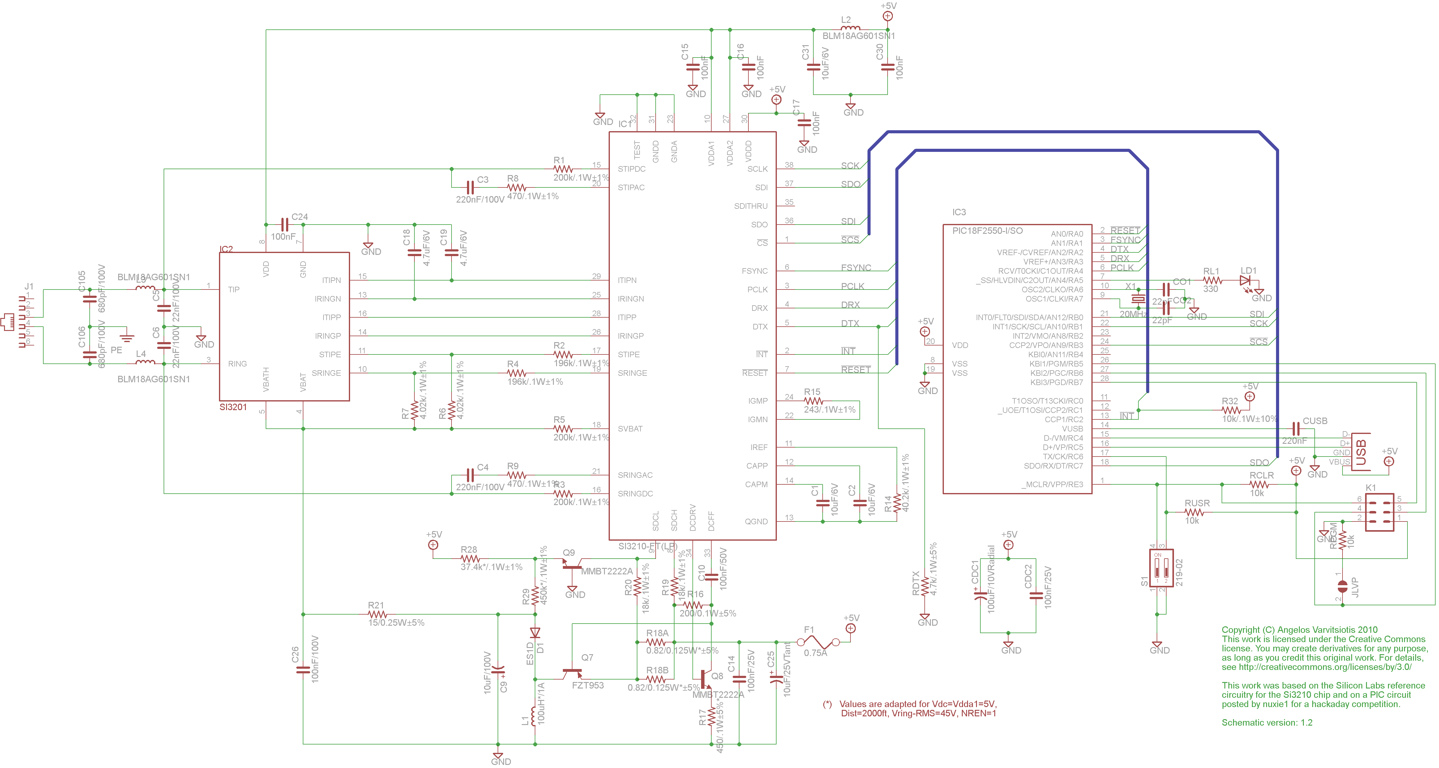
dyi setup and debugging guide
This page discusses the differences between assembled Open USB FXS dongle boards and DIY boards. While the assembled boards are fully tested and quality control approved, DIY boards may encounter various issues during assembly. Fortunately, most of these issues can...
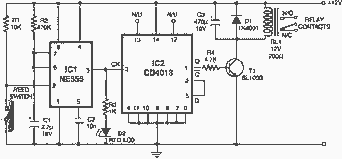
Magnetic proximity sensor / detector
Here is an interesting circuit for a magnetic proximity switch which can be used in various applications. The magnetic proximity switch circuit, in principle, consists of a reed switch at its heart. When a magnet is brought in the vicinity...
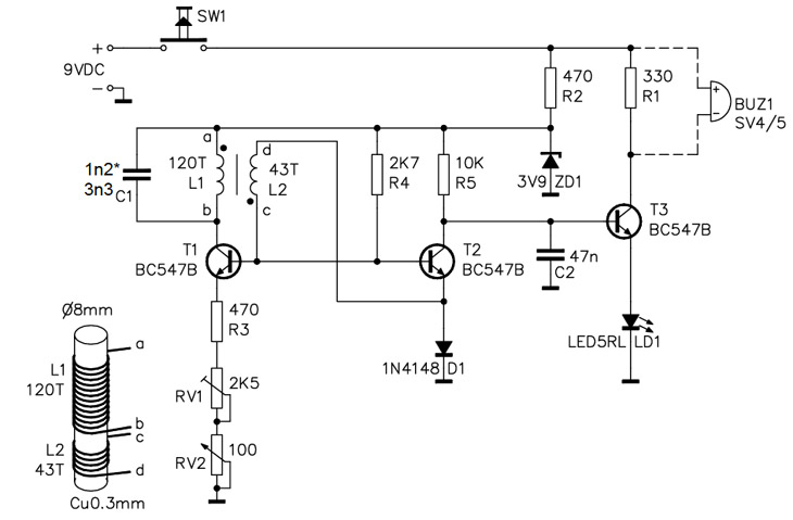
Homemade Metal Detector Kit
A simple home project can quickly become problematic if it encounters electric cables, gas, or water pipes, or the central heating system. Using a metal detector allows one to check for metal objects within walls, ceilings, or floors beforehand. An...
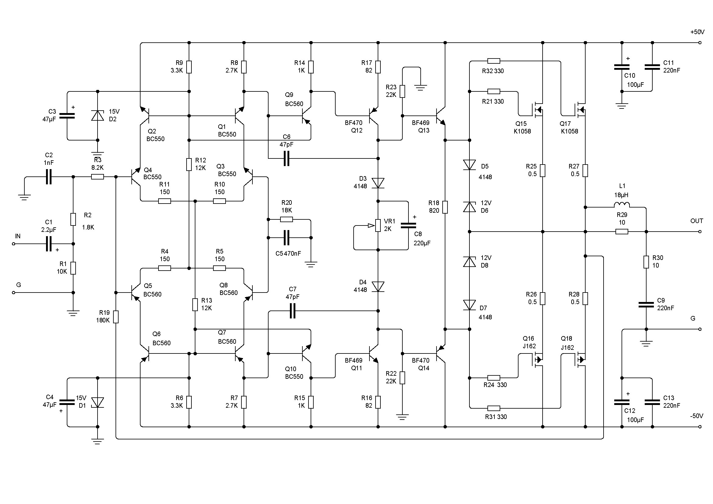
Crescendo ampilifier elektor1982
The Elector Crescendo was the first DIY amplifier that was not a kit. The design was sourced from the Elector magazines available at a local library.
The Elector Crescendo is an innovative audio amplifier designed for DIY enthusiasts. It features a...
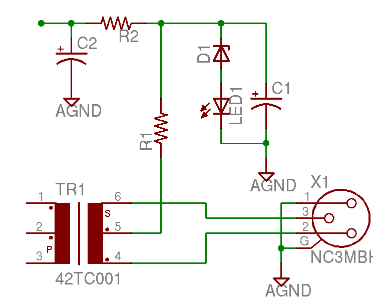
Help with a schematic please
A project is underway to construct the CountryHick DI as illustrated on DIYFactory, incorporating a few minor modifications. The final design aims to be a 1U unit with four inputs.
The CountryHick DI (Direct Injection) box is a crucial tool in...
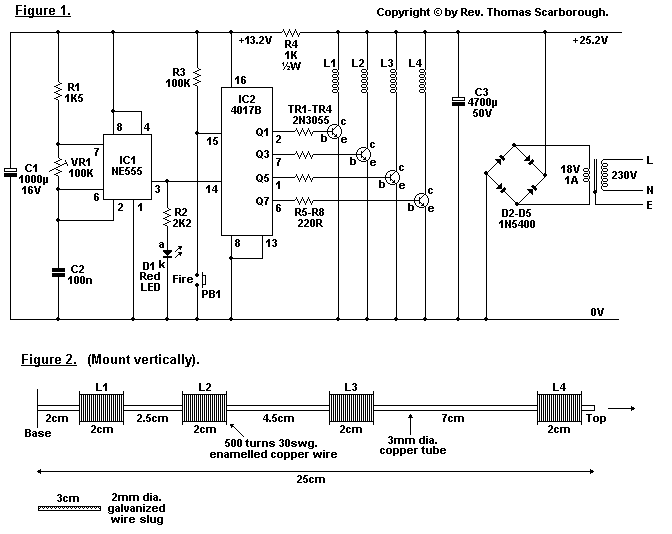
magnetic gun
When optimally tuned, it will propel a small slug about 1.5 meters high or 2.5 meters horizontally.
The described mechanism appears to be a projectile propulsion system capable of launching a small slug, likely a lightweight object, to specific heights and...
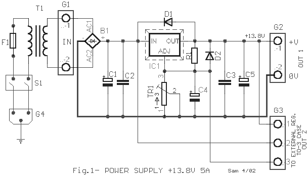
Electronics Projects Circuits
Over 1400 top electronics projects and electronic circuits with photos, datasheets, and easy-to-read schematics, along with explanations of how they work and how to build them.
The collection comprises a vast array of electronics projects suitable for enthusiasts and professionals alike....
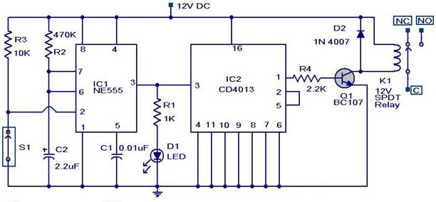
Magnetic Proximity Switch Circuit
This weblog discusses electronic circuit schematics, PCB design, DIY kits, and electronic project diagrams. The circuit diagram presented is for a magnetic proximity switch, which has numerous applications across various fields. The circuit utilizes a magnetic reed switch (S1) as...
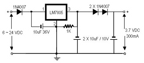
how to convert a 9v battery to 3.7v
A regulator circuit is needed for this DIY project. Familiarity with electronic components, circuitry, the use of a multitester, and a soldering iron is essential. The schematic diagram provided can accept an input voltage ranging from 6 to 24 volts...