


Odd application of neon glow lamps
#neon glow lamp
#diac
#voltage trigger
#U/I characteristic
#high voltage
#electronic component
#non-linear device
#trigger device
#voltage drop
#current flow
Description: Neon glow lamps can be utilized solely for their voltage/current characteristics rather than for illumination. These lamps are electrically similar to diacs; no current flows through them when the voltage is below a trigger value (approximately 70V for neon glow lamps and about 40V for diacs). When the voltage exceeds the trigger level, current can flow, resulting in a voltage drop slightly lower than the trigger voltage (around 50V for neon glow lamps and about 30V for diacs). In a dimmer circuit, a neon glow lamp can replace a diac, functioning in the same manner as a traditional diac: an RC network delays the trigger pulses at the gate of the triac. The glow lamp increases the trigger voltage from approximately 40V to about 70V. Adjustments to the resistor and capacitor values may be necessary to accommodate specific glow lamps and triacs. A stroboscope is another application that utilizes a diac (or a neon glow lamp) to trigger a xenon tube: this circuit employs a neon glow lamp but operates similarly to a conventional diac circuit. The main voltage is rectified by a diode and charges two electrolytic high-voltage capacitors (in parallel), which serve as an energy reservoir for the xenon lamp. Additionally, current flows through a resistor to gradually charge a trigger capacitor. When the voltage reaches the trigger threshold of the glow lamp, the SCR discharges this capacitor through a trigger transformer into the xenon lamp, causing it to flash. Once the energy in the reservoir is depleted, this cycle repeats; the frequency can be adjusted by varying the resistance that charges the trigger capacitor. It is crucial to note that the energy stored in the electrolytic capacitors can be lethal even when the circuit is powered off. Therefore, these capacitors should always be discharged before any contact with the circuit. An unusual application of a neon glow lamp involves its use as an electromagnetic field detector. The trigger voltage of these lamps decreases slightly in the presence of a strong electromagnetic field. A UJT transistor and a transformer (typically a low power AC transformer) are employed to generate a high voltage of approximately 200Vac. This voltage is then reduced by a trimmer to a value just below the trigger voltage of the lamp. In the presence of a strong field, the trigger voltage lowers, causing the lamp to illuminate. To utilize this monitor, set the trimmer to 0V, power on the circuit (with no field present), and gradually adjust the trimmer to increase the voltage until the glow lamp lights. Then, turn the trimmer in the opposite direction, stopping as soon as the lamp turns off; the monitor is now calibrated to detect strong RF fields, which will illuminate the bulb. Testing can be conducted using a cellular phone or a transmitter (requiring several watts of power), with the bulb illuminating in proximity to the antenna.
Neon glow lamps serve dual purposes in electronic circuits: they can function as indicators or as components in triggering mechanisms, capitalizing on their unique voltage/current characteristics. In dimmer circuits, they effectively replace diacs to control the operation of triacs, contributing to the regulation of power delivered to lighting systems. The implementation of an RC network allows for precise timing adjustments, ensuring that the triac is triggered at the desired moment, thus facilitating smooth dimming capabilities.
In stroboscope applications, the neon glow lamp's ability to act as a trigger is essential for the operation of xenon tubes, which produce brief bursts of light. This functionality is vital in photography and entertainment, where synchronized flashes are required. The careful design of the charging circuit, utilizing high-voltage capacitors, ensures that sufficient energy is stored to produce the desired flash intensity.
The innovative use of neon glow lamps as electromagnetic field detectors highlights their versatility beyond conventional applications. By integrating simple components such as UJT transistors and transformers, these lamps can be transformed into sensitive monitoring devices. The calibration process involving a trimmer allows users to fine-tune the sensitivity of the detector, making it a practical tool for identifying electromagnetic interference from various sources, including communication devices.
Safety precautions are paramount when working with circuits involving high-voltage components such as electrolytic capacitors. Proper discharge methods must be implemented to prevent accidental electric shock, ensuring safe handling during maintenance and testing. Overall, the multifaceted applications of neon glow lamps illustrate their importance in both practical and experimental electronic designs.Neon glow lamps can also be used only for their U/I characteristic and not for producing light. These lamps are electrically very close to diacs: no current can flow through them since the voltage is lower than a trigger value (about 70V for neon glow lamps and about 40V for diacs). If the voltage is high enough to trigger the device a current can flow through it and the voltage drop
is a little lower than the trigger voltage (about 50V for neon glow lamps and about 30V for diacs). In this circuit of a dimmer the diac is replaced with a neon glow lamp, but it works exactly in the same way than a classic one: an RC network delays the trigger pulses on the gate of the triac. The glow lamp rises the trigger voltage from about 40V to about 70V. Some adjustments to R and C values may be required to match specific glow lamps and triacs. A stroboscope is another application that requires a diac (or a neon glow lamp) for triggering the xenon tube: this circuit uses a neon glow lamp but it works in the same way as a classic diac one.
The main voltage is rectified by a diode and charges two electrolytic high voltage capacitors (in parallel) that are used as an energy tank for the xenon lamp. A current also flows though a resistor and slowly charges a trigger capacitor: when the voltages reaches the trigger value of the glow lamp the SCR discharges this capacitor through a trigger transformer into the xenon lamp that flashes.
Once the energy in the tank is over this cycle repeats; the frequency is adjusted by varying the resistance that charges the trigger capacitor. The energy in the electrolytic capacitors can be lethal even when the circuit is switched off. Always discharge these capacitors before touching the circuit. This is the oddest application of a neon glow lamp, that is used as a electromagnetic field detector.
In fact the trigger voltage of these lamps is a little bit lower in presence of a strong field. A UJT transistor and a transformer (a common low power AC transformer) are used to produce a high voltage of about 200Vac. This voltage is reduced by the trimmer to a value just below the trigger voltage of the lamp. In presence of a strong field the trigger voltage drops and the lamp lights. To use this monitor just set the trimmer to 0V, power the circuit on (when no field is present) and slowly turn the trimmer to rise the voltage until the glow lamp lights.
Turn now the trimmer in the other direction and stop as soon as the lamp turns off: now the monitor is ready and a strong RF field will light the bulb. For testing you can try a cellular phone or a transmitter (some Watts of power are required) and the bulb will light in proximity of the antenna.
Neon glow lamps serve dual purposes in electronic circuits: they can function as indicators or as components in triggering mechanisms, capitalizing on their unique voltage/current characteristics. In dimmer circuits, they effectively replace diacs to control the operation of triacs, contributing to the regulation of power delivered to lighting systems. The implementation of an RC network allows for precise timing adjustments, ensuring that the triac is triggered at the desired moment, thus facilitating smooth dimming capabilities.
In stroboscope applications, the neon glow lamp's ability to act as a trigger is essential for the operation of xenon tubes, which produce brief bursts of light. This functionality is vital in photography and entertainment, where synchronized flashes are required. The careful design of the charging circuit, utilizing high-voltage capacitors, ensures that sufficient energy is stored to produce the desired flash intensity.
The innovative use of neon glow lamps as electromagnetic field detectors highlights their versatility beyond conventional applications. By integrating simple components such as UJT transistors and transformers, these lamps can be transformed into sensitive monitoring devices. The calibration process involving a trimmer allows users to fine-tune the sensitivity of the detector, making it a practical tool for identifying electromagnetic interference from various sources, including communication devices.
Safety precautions are paramount when working with circuits involving high-voltage components such as electrolytic capacitors. Proper discharge methods must be implemented to prevent accidental electric shock, ensuring safe handling during maintenance and testing. Overall, the multifaceted applications of neon glow lamps illustrate their importance in both practical and experimental electronic designs.Neon glow lamps can also be used only for their U/I characteristic and not for producing light. These lamps are electrically very close to diacs: no current can flow through them since the voltage is lower than a trigger value (about 70V for neon glow lamps and about 40V for diacs). If the voltage is high enough to trigger the device a current can flow through it and the voltage drop
is a little lower than the trigger voltage (about 50V for neon glow lamps and about 30V for diacs). In this circuit of a dimmer the diac is replaced with a neon glow lamp, but it works exactly in the same way than a classic one: an RC network delays the trigger pulses on the gate of the triac. The glow lamp rises the trigger voltage from about 40V to about 70V. Some adjustments to R and C values may be required to match specific glow lamps and triacs. A stroboscope is another application that requires a diac (or a neon glow lamp) for triggering the xenon tube: this circuit uses a neon glow lamp but it works in the same way as a classic diac one.
The main voltage is rectified by a diode and charges two electrolytic high voltage capacitors (in parallel) that are used as an energy tank for the xenon lamp. A current also flows though a resistor and slowly charges a trigger capacitor: when the voltages reaches the trigger value of the glow lamp the SCR discharges this capacitor through a trigger transformer into the xenon lamp that flashes.
Once the energy in the tank is over this cycle repeats; the frequency is adjusted by varying the resistance that charges the trigger capacitor. The energy in the electrolytic capacitors can be lethal even when the circuit is switched off. Always discharge these capacitors before touching the circuit. This is the oddest application of a neon glow lamp, that is used as a electromagnetic field detector.
In fact the trigger voltage of these lamps is a little bit lower in presence of a strong field. A UJT transistor and a transformer (a common low power AC transformer) are used to produce a high voltage of about 200Vac. This voltage is reduced by the trimmer to a value just below the trigger voltage of the lamp. In presence of a strong field the trigger voltage drops and the lamp lights. To use this monitor just set the trimmer to 0V, power the circuit on (when no field is present) and slowly turn the trimmer to rise the voltage until the glow lamp lights.
Turn now the trimmer in the other direction and stop as soon as the lamp turns off: now the monitor is ready and a strong RF field will light the bulb. For testing you can try a cellular phone or a transmitter (some Watts of power are required) and the bulb will light in proximity of the antenna.
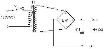
High Voltage High Current Power Supply
The circuit can produce about 250-500mA at 2KV, depending on the transformer. For C1, you can use the capacitor out of an old microwave. This circuit is mainly provided as a demonstration of using commonly available parts for something uncommon....

High voltage stable power supply
The schematic diagram originates from a circuit designed for a stable power supply ranging from -100V to -1000V. For further details, refer to the page that explains the circuit diagram associated with this power supply. This stable power supply serves...
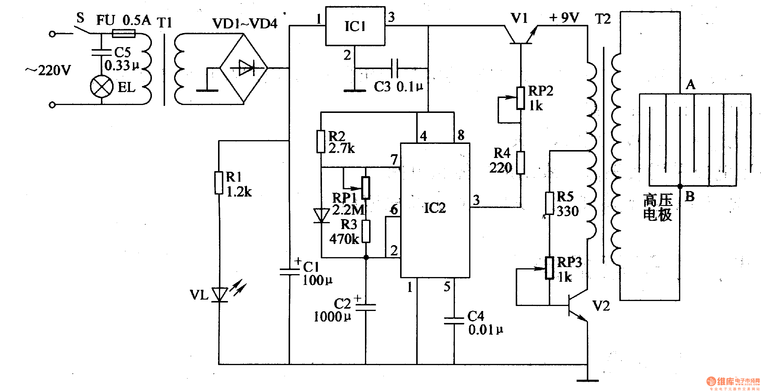
Electronic Pest Killing Lamp
Working Principle: The circuit, as illustrated in figure 4-187, is composed of three main components: the power circuit, the pulse oscillator, and the high voltage generator. The power circuit includes components S, FU, TI, VD1-VD4, C1, C3, IC1, R1, and...
electricity
According to the datasheet, they will switch about 160 kW at up to 10 kV (7.2 kV typical). Unfortunately, this is insufficient for the quarter shrinker; however, a miniature ring flipper may be in development. A presentation will be held...
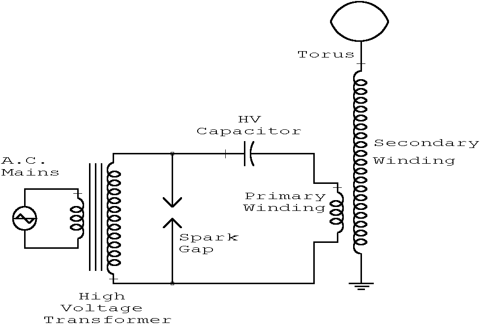
Tesla Coil
This webpage is designed to provide assistance and information for individuals interested in constructing a Tesla coil. It is recommended to utilize the additional resources available on this page. The electrical line voltage standard in the United States is 120V...
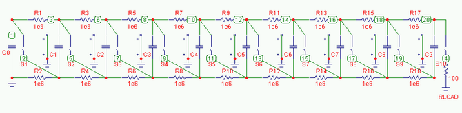
Marx Generators
Marx Generators are commonly utilized in pulsed power and high voltage applications to produce a high peak voltage pulse. The fundamental principle behind these generators involves charging several capacitors in parallel, followed by closing switches to connect them in series....
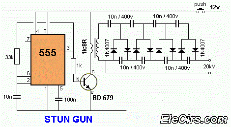
12V to 20KV inverter circuit diagram using IC555 STUN GUN
A 12V to 20000V inverter circuit diagram (stun gun) is presented. This circuit generates a very high voltage and must be used with caution to prevent electric shock. The transformer can produce over 1000V and amplify the voltage by eight...
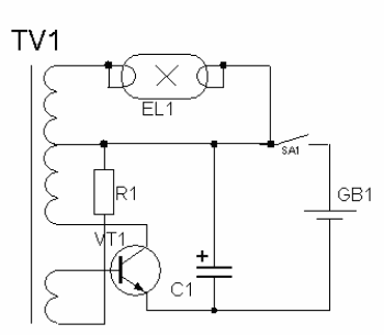
high voltage power supply circuit for fluorescent light
High-voltage power supply circuit for fluorescent light power supply. Refer to that page for an explanation of the related circuit diagram.
The high-voltage power supply circuit designed for fluorescent lights typically consists of several key components that work together to convert...
Gray Tube Replication 74
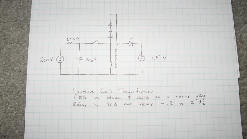
Geotron, I have damaged a few components myself. What type of bridge do you have connected to it? When I used a 1kV bridge made from four 6A100 diodes, I encountered issues.
In this context, the discussion revolves around the use...