


quick electronics designs
#serial adaptor
#RS232
#connector
#cable
#electronics tool
#male-male
#male-female
#female-female
#serial port
#monitoring
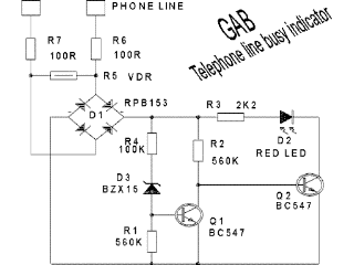
Description: Connect all connectors onto the flat cable using a small vice. This creates an instant male-male, male-female, and female-female serial adapter, along with a short extender cord. This tool is essential for those experimenting with serial ports. An additional connector can be added for monitoring RS232 traffic. A tip shared by Randy Rhoade suggests that connecting a null modem between the connectors at one end transforms the setup into a loop-back tester. This circuit design was created by Gabriele Bandini, who has a home filled with telephones, modems, and children. After experiencing multiple modem failures, he decided to add an indicator LED to each phone plug to alert the family when the phone line is free. This circuit is beneficial for users with both a fax machine and a phone on the same line, as it indicates when making a phone call will not disrupt an incoming fax. For users with an internal modem, this circuit indicates when it is on-hook. It should be noted that this circuit is intended for use with Italian telephones, and prior written approval from the phone company is required before installation on the phone line.
Additionally, the design repurposes an old LCD alarm clock, although it is likely compatible with LED types as well. It serves various functions, such as watering plants or precisely controlling heating, garden lights, or a Christmas tree. The circuit operates simply: the activating signal is taken in parallel from the original buzzer (which can be removed). When the alarm activates, the set/reset flip-flop is set. The output of the flip-flop is connected to the reset input via a delay network consisting of a 10 MΩ resistor and a 1000 µF capacitor. This configuration allows the flip-flop to reset itself after a delay of approximately three hours, making it ready for a new activation cycle. The delay can be adjusted to any desired length, from seconds to hours, by modifying the resistor and/or capacitor values.
Replacing the LED with an optocoupler enables monitoring of appliance or industrial equipment operation via a PC's serial or parallel port, with the output providing a square wave at mains frequency. The amperometric transformer (TA) used in the prototype is a 200:1, 5A maximum toroidal transformer, originally intended for current measurement. The primary winding (black wire on the left) originally had 2 turns, but a new winding with 4 turns was added to enhance sensitivity (represented by the white wire on top). In Italy, household mains power is typically limited to 3 kW, and with devices like hairdryers consuming up to 1900W, it is crucial to monitor power usage to avoid tripping the mains circuit breaker.
This priority switch circuit is designed to automatically cut power to appliance B when appliance A is powered on, ensuring that appliance A takes precedence and the total power consumption remains within safe limits. A notable feature of this circuit is that it does not require an external power supply and consumes no power when inactive. When current flows through the TA, the LED in the phototriac lights up, triggering the triac to activate the relay that disconnects load B. It is important to note that a zero-crossing optotriac should not be used with this circuit.Snap all connectors on to the flat cable (a small vice will do the job). You get an instant male-male, male-female, female-female serial adaptor, plus a short extender cord. A must-have tool if you`re planning to play with serial ports. You can even put an extra connector for monitoring the RS232 traffic. Another nice tip sent by Randy Rhoade s: did you know that if you connected a null modem between the connectors on one of the ends, the Snake becomes a loop-back tester This circuit has been designed by Gabriele Bandini. His home is full of telephones, modems, and. kids. After a dozen of modem crashes, he decided to put an indicator LED on every phone plug to show to the family when the phone line is free.
If you have a FAX and a phone on the same line, this circuit can show you when to make a phone call without disrupting an incoming fax. If you have an internal modem, this circuit will show you when it is on hook Note that this circuit is designed to work with italian telephones and that you need the written approval of your phone company prior to put something on the phone line.
If you don`t have noticed it yet, I like to reuse hardware objects. This design brings new life to an old lcd alarm clock (but I bet it would work with LED types too). It is useful for a variety of purposes, from watering your flowers to (precisely) switch on the heating, the garden lights or even your christmas tree! The circuit cannot be simpler: the activating signal is picked up in parallel from the original buzzer (that can even be removed).
When the alarm "sounds", the set/reset flip flop is SET. The flip-flop output is also connected to the RESET input, through a 10Mohm x 1000uF delay network. This means that, after the delay time (about three hours on my prototype), the flip-flop resets itself. The daily timer is then ready for a new activation. You can set any delay you like, from seconds to hours, simply adjusting the resistor and/or capacitor values.
Replace the LED with an optocoupler and connect it to the PC serial or parallel port to monitor when an appliance or an industrial equipement is working (the output is a square wave at mains frequency) The amperometric transformer (TA) on my prototype is a 200:1, 5A max. toridal transformer, originally made for current measurement. The primary (black wire on the left) had 2 turns, but I have wound a new one with 4 turns in order to increase sensitivity (it is the white wire on top).
Here in Italy, the amount of mains power for most households is limited to 3 kW. With an hairdryer taking as much power as 1900W, I must check not to exceed the maximum power rating every time I switch on an electric appliance. Failing to do it may result in an unplanned walk out of the home, to restore the mains circuit breaker switch.
I use this priority switch to automatically remove power from appliance B when A is powered on. That is, A takes precedence over B, and the maximum power consumption is never execeeded. One nice feature of this circuit is it does not require an external power supply, and it consumes nothing when not active. When current flows in the TA, the LED in the phototriac lits, and the triac turns on the relay disconnecting load B.
Do NOT use a zero-crossing optotriac with this circuit.
Additionally, the design repurposes an old LCD alarm clock, although it is likely compatible with LED types as well. It serves various functions, such as watering plants or precisely controlling heating, garden lights, or a Christmas tree. The circuit operates simply: the activating signal is taken in parallel from the original buzzer (which can be removed). When the alarm activates, the set/reset flip-flop is set. The output of the flip-flop is connected to the reset input via a delay network consisting of a 10 MΩ resistor and a 1000 µF capacitor. This configuration allows the flip-flop to reset itself after a delay of approximately three hours, making it ready for a new activation cycle. The delay can be adjusted to any desired length, from seconds to hours, by modifying the resistor and/or capacitor values.
Replacing the LED with an optocoupler enables monitoring of appliance or industrial equipment operation via a PC's serial or parallel port, with the output providing a square wave at mains frequency. The amperometric transformer (TA) used in the prototype is a 200:1, 5A maximum toroidal transformer, originally intended for current measurement. The primary winding (black wire on the left) originally had 2 turns, but a new winding with 4 turns was added to enhance sensitivity (represented by the white wire on top). In Italy, household mains power is typically limited to 3 kW, and with devices like hairdryers consuming up to 1900W, it is crucial to monitor power usage to avoid tripping the mains circuit breaker.
This priority switch circuit is designed to automatically cut power to appliance B when appliance A is powered on, ensuring that appliance A takes precedence and the total power consumption remains within safe limits. A notable feature of this circuit is that it does not require an external power supply and consumes no power when inactive. When current flows through the TA, the LED in the phototriac lights up, triggering the triac to activate the relay that disconnects load B. It is important to note that a zero-crossing optotriac should not be used with this circuit.Snap all connectors on to the flat cable (a small vice will do the job). You get an instant male-male, male-female, female-female serial adaptor, plus a short extender cord. A must-have tool if you`re planning to play with serial ports. You can even put an extra connector for monitoring the RS232 traffic. Another nice tip sent by Randy Rhoade s: did you know that if you connected a null modem between the connectors on one of the ends, the Snake becomes a loop-back tester This circuit has been designed by Gabriele Bandini. His home is full of telephones, modems, and. kids. After a dozen of modem crashes, he decided to put an indicator LED on every phone plug to show to the family when the phone line is free.
If you have a FAX and a phone on the same line, this circuit can show you when to make a phone call without disrupting an incoming fax. If you have an internal modem, this circuit will show you when it is on hook Note that this circuit is designed to work with italian telephones and that you need the written approval of your phone company prior to put something on the phone line.
If you don`t have noticed it yet, I like to reuse hardware objects. This design brings new life to an old lcd alarm clock (but I bet it would work with LED types too). It is useful for a variety of purposes, from watering your flowers to (precisely) switch on the heating, the garden lights or even your christmas tree! The circuit cannot be simpler: the activating signal is picked up in parallel from the original buzzer (that can even be removed).
When the alarm "sounds", the set/reset flip flop is SET. The flip-flop output is also connected to the RESET input, through a 10Mohm x 1000uF delay network. This means that, after the delay time (about three hours on my prototype), the flip-flop resets itself. The daily timer is then ready for a new activation. You can set any delay you like, from seconds to hours, simply adjusting the resistor and/or capacitor values.
Replace the LED with an optocoupler and connect it to the PC serial or parallel port to monitor when an appliance or an industrial equipement is working (the output is a square wave at mains frequency) The amperometric transformer (TA) on my prototype is a 200:1, 5A max. toridal transformer, originally made for current measurement. The primary (black wire on the left) had 2 turns, but I have wound a new one with 4 turns in order to increase sensitivity (it is the white wire on top).
Here in Italy, the amount of mains power for most households is limited to 3 kW. With an hairdryer taking as much power as 1900W, I must check not to exceed the maximum power rating every time I switch on an electric appliance. Failing to do it may result in an unplanned walk out of the home, to restore the mains circuit breaker switch.
I use this priority switch to automatically remove power from appliance B when A is powered on. That is, A takes precedence over B, and the maximum power consumption is never execeeded. One nice feature of this circuit is it does not require an external power supply, and it consumes nothing when not active. When current flows in the TA, the LED in the phototriac lits, and the triac turns on the relay disconnecting load B.
Do NOT use a zero-crossing optotriac with this circuit.
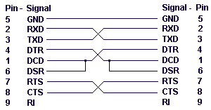
RS232 cable modem
First of all you have to build one cable adapter to connect the female 9pins connector of the modem, with female 9pins connector of the base of E-10G HPC. To build the null modem cable you will need: 2 male...
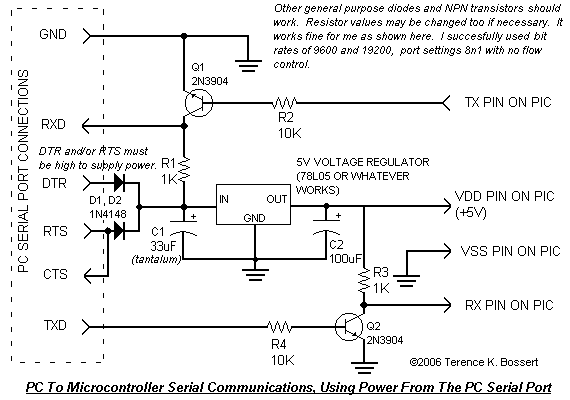
RS232 Dev Board
A simple RS232 example project that draws all its power from the serial port. It is designed to power a microcontroller and facilitate communication between the serial port and the microcontroller. This project utilizes the capability of PC serial ports...
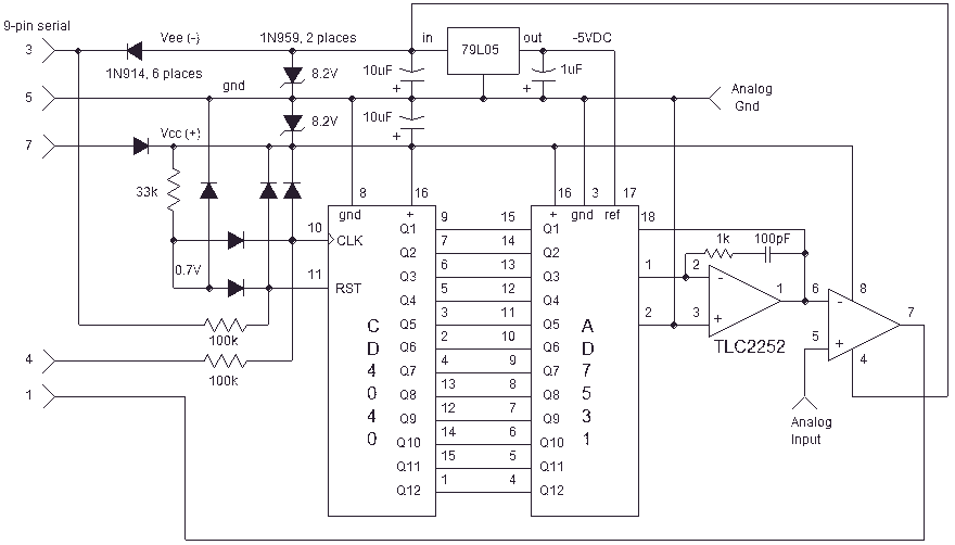
Computer Serial Port interface
Here is an inexpensive way to get slow-moving analog data directly into a spreadsheet on your computer! A simple circuit connects to a serial port and a short Qbasic program gathers and saves 12 bit data to a file. A...
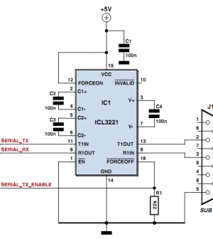
network rs232
A significant number of modules still utilize an RS232 interface. This is understandable, as RS232 can be easily implemented on a microcontroller using just two I/O pins and a line driver such as the MAX232. When the master device is...
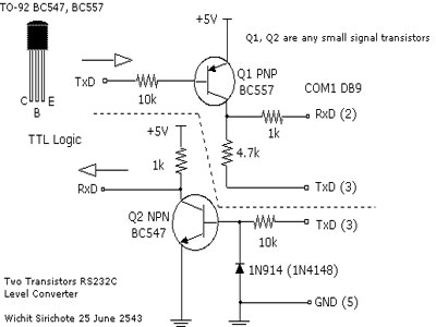
Simple RS 232 Level Converter
When connecting a microcontroller project to a COM port on a PC, an RS-232 converter is required. Various chips can accomplish this task, such as the MAX232 and DS275. However, for a simple and cost-effective RS-232 converter, the following circuit...
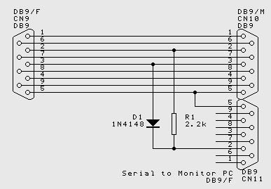
RS232 Connections wiring up
While the normal PC hardware might well run with just Tx, Rx and Ground connected, most driver software will wait forever for one of the handshaking lines to go to the correct level. Depending on the signal state it might...
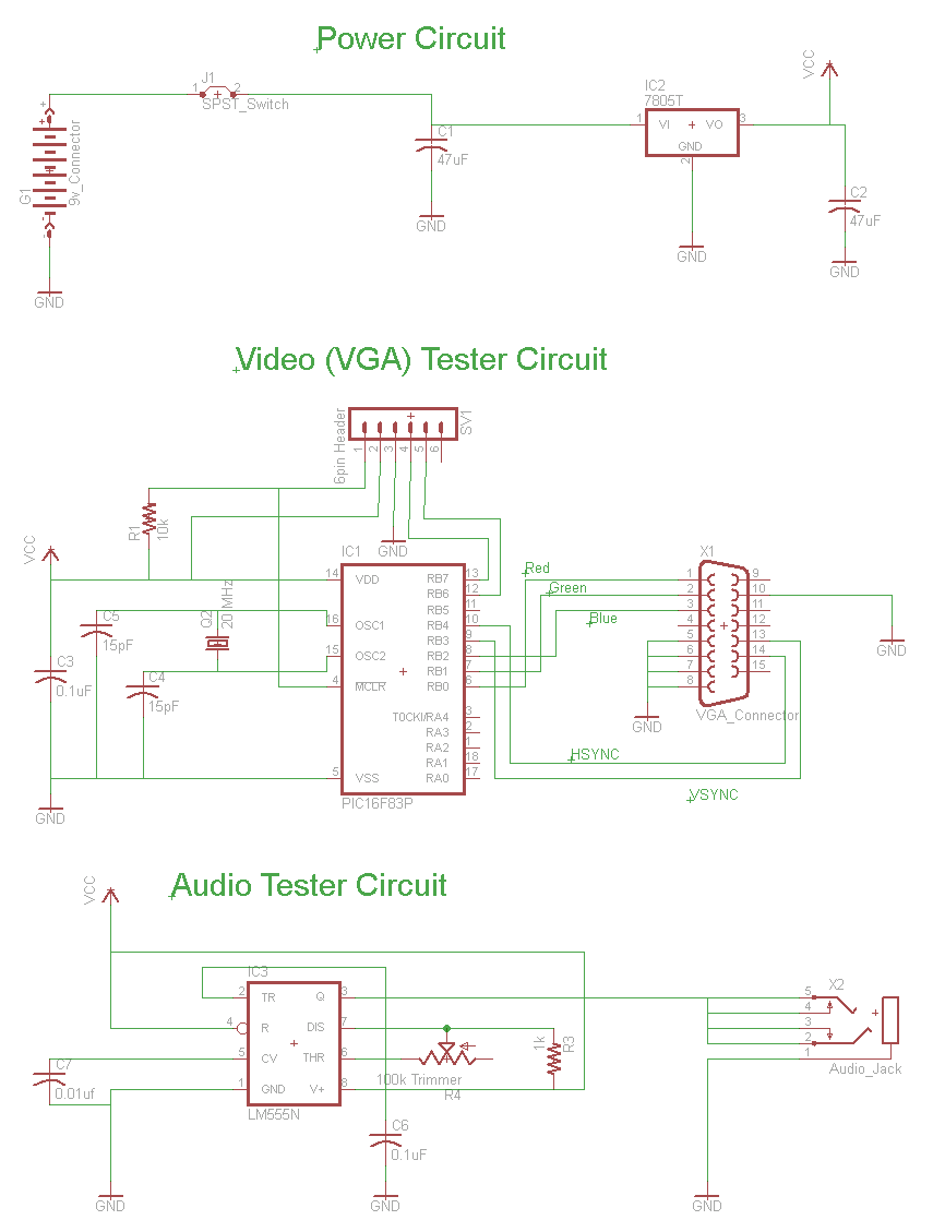
Simple RS232 Serial Interface Circuit
The circuit for the RS232 serial interface exhibits mild complexity. The primary components of the circuit include the 18F4520 microcontroller, MAX233A level shifter, and a DB-9 connector. This circuit utilizes a basic +5V power regulator to supply the digital signals...
powering circuit using serial port
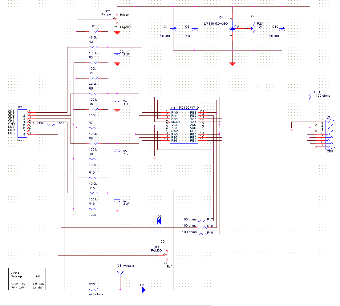
Power an RS232-TTL converter circuit using the serial port to eliminate the need for an external power supply. It has been noted that the DTR, RTS, and TD pins can facilitate this. Since the TD pin is already utilized for...
Interface between Ericsson 6xx/7xx phones and a PC
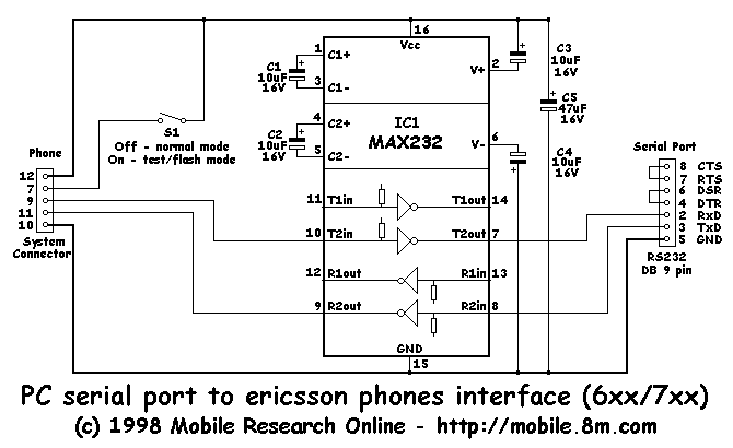
This interface is needed to connect the phone to a PC, because the PC's serial port works with voltage levels between -12 and 12V (RS232 protocol) and the phone operates between 0 and 5V (TTL protocol). Don't even think of...