


SG3525A Pulse Width Modulator Control Circuits
#SG3525A
#PWM
#control circuit
#DCDC converter
#analog
#power supply
#switching
#voltage regulation
#modulator
#circuit design
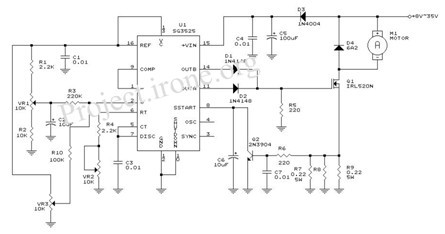
Description: This article explains the principle of the Audison LR604XR amplifier. The principle is straightforward; it is recommended to combine the text with a careful reading of the complete schematic. To fully understand this principle, it is advisable to review it multiple times. The layout includes a DC-DC converter and analog components. The SG3525A pulse width modulator controls circuits to enhance performance and reduce the external parts count when applied to various types of switching power supplies. The on-chip +5.1 V reference is trimmed to ±1%, and the error amplifier features an input common. The SG3525 DC Converter operates within a range of 12V to +35V and -35V. The chosen switching topology is known as a "push-pull" converter, as the transformer has a dual primary winding (or a "center-tapped" configuration). The center tap is permanently connected to the circuit. The PWM DC motor control using the SG3525 circuit diagram is part of a series of PWM designs, which are ideal for precise control of DC motors. This involves converting DC voltage into a series of pulses, with the pulse duration being directly proportional to the DC voltage value. A significant advantage of this circuit is its efficiency in controlling DC motors.
The Audison LR604XR amplifier utilizes a straightforward yet effective design principle that integrates a DC-DC converter and analog circuitry. The SG3525A pulse width modulator serves as the heart of the control mechanism, enabling improved performance and a reduced count of external components. This modulator is particularly beneficial for various switching power supply applications due to its efficiency and reliability.
In the schematic, the SG3525A is configured to provide a regulated output voltage, leveraging its on-chip +5.1 V reference, which is precisely trimmed to ensure minimal deviation. The error amplifier within the SG3525A monitors the output voltage, adjusting the duty cycle of the PWM signal to maintain the desired output level.
The push-pull converter topology employed in this design allows for effective voltage conversion, utilizing a transformer with dual primary windings. This configuration enables the efficient transfer of energy, minimizing losses and maximizing output power. The center tap connection ensures that the circuit can effectively manage the alternating current flow necessary for the push-pull operation.
Furthermore, the PWM control of DC motors using this configuration allows for accurate speed regulation. The circuit converts the DC voltage into a series of pulses, where the duration of each pulse correlates directly with the input voltage. This method provides a high level of control over the motor's speed and torque, making it suitable for applications requiring precise motor management.
Overall, the combination of the SG3525A modulator and the push-pull converter topology in the Audison LR604XR amplifier design exemplifies a robust solution for audio amplification and motor control, showcasing efficiency, precision, and adaptability in various electronic applications.This article describes an amplifier Audison LR604XR principle. The principle is simple there, we recommend that combine text carefully read the complete schematic. To better grasp this principle, it is recommended to read several times on this principle. 1. Layout DCDC converter and analog par. The SG3525A pulse width modulator control circuits off er improved performance and lower external parts count when implemented for controlling all types of switching power supplies. The on–chip +5. 1 V reference is trimmed to ±1% and the error amplifier has an input common&nda. SG3525 DC Converter 12V to +35V, -35V SG3525 DC Converter 12V to +35V, -35V The selected switching topology is called a "push-pull" converter, because the transformer has a double primary (or a "center-tapped" one, if your prefer).
The center tap is permanently connected to the c. PWM DC motor using SG3525Circuit diagram is one of a series of PWM. Circuit diagram is ideal for accurate control of DC motors. DC voltage conversion to a series of pulses, such that the duration of the pulse is a direct proportion to the value of DC voltage. Big advantage as the circuit is that alm. Circuit diagram is one of a series of PWM. Circuit diagram is ideal for accurate control of DC motors. conversion of DC voltage pulses to the circuit IC is controlled by SG3525, such that the pulse duration is directly proportion to the value of DC voltage.
Big advantage as the circuit is that alm.
The Audison LR604XR amplifier utilizes a straightforward yet effective design principle that integrates a DC-DC converter and analog circuitry. The SG3525A pulse width modulator serves as the heart of the control mechanism, enabling improved performance and a reduced count of external components. This modulator is particularly beneficial for various switching power supply applications due to its efficiency and reliability.
In the schematic, the SG3525A is configured to provide a regulated output voltage, leveraging its on-chip +5.1 V reference, which is precisely trimmed to ensure minimal deviation. The error amplifier within the SG3525A monitors the output voltage, adjusting the duty cycle of the PWM signal to maintain the desired output level.
The push-pull converter topology employed in this design allows for effective voltage conversion, utilizing a transformer with dual primary windings. This configuration enables the efficient transfer of energy, minimizing losses and maximizing output power. The center tap connection ensures that the circuit can effectively manage the alternating current flow necessary for the push-pull operation.
Furthermore, the PWM control of DC motors using this configuration allows for accurate speed regulation. The circuit converts the DC voltage into a series of pulses, where the duration of each pulse correlates directly with the input voltage. This method provides a high level of control over the motor's speed and torque, making it suitable for applications requiring precise motor management.
Overall, the combination of the SG3525A modulator and the push-pull converter topology in the Audison LR604XR amplifier design exemplifies a robust solution for audio amplification and motor control, showcasing efficiency, precision, and adaptability in various electronic applications.This article describes an amplifier Audison LR604XR principle. The principle is simple there, we recommend that combine text carefully read the complete schematic. To better grasp this principle, it is recommended to read several times on this principle. 1. Layout DCDC converter and analog par. The SG3525A pulse width modulator control circuits off er improved performance and lower external parts count when implemented for controlling all types of switching power supplies. The on–chip +5. 1 V reference is trimmed to ±1% and the error amplifier has an input common&nda. SG3525 DC Converter 12V to +35V, -35V SG3525 DC Converter 12V to +35V, -35V The selected switching topology is called a "push-pull" converter, because the transformer has a double primary (or a "center-tapped" one, if your prefer).
The center tap is permanently connected to the c. PWM DC motor using SG3525Circuit diagram is one of a series of PWM. Circuit diagram is ideal for accurate control of DC motors. DC voltage conversion to a series of pulses, such that the duration of the pulse is a direct proportion to the value of DC voltage. Big advantage as the circuit is that alm. Circuit diagram is one of a series of PWM. Circuit diagram is ideal for accurate control of DC motors. conversion of DC voltage pulses to the circuit IC is controlled by SG3525, such that the pulse duration is directly proportion to the value of DC voltage.
Big advantage as the circuit is that alm.
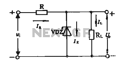
Regulator circuit silicon resistor formed
The simple voltage regulator circuit consists of a silicon regulator and a resistor. It is designed to rectify and filter DC voltage, as illustrated in the accompanying figure. The voltage regulator is connected in parallel with the load, and the...
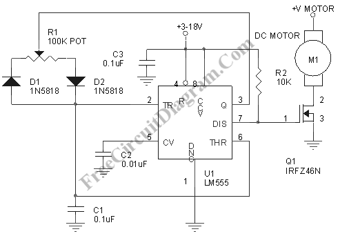
Motor Speed Control Using PWM
Pulse width modulation, commonly referred to as PWM, is utilized to regulate the power supplied to a load without sacrificing efficiency. This technique is often employed in controlling the speed of an electric motor.
PWM operates by varying the width of...
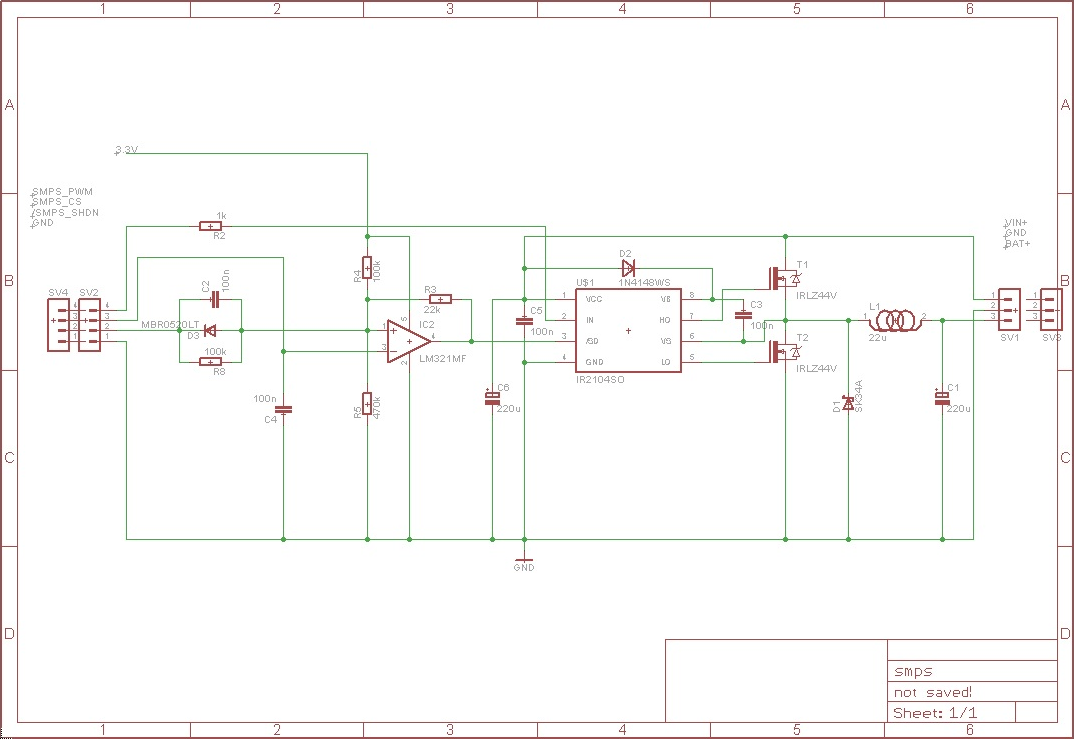
pwm Why is the MOSFET driver in this circuit dying
The circuit receives an input voltage (Vin), which is processed through a Switch Mode Power Supply (SMPS) utilizing two MOSFETs driven by an IR2104 driver. The output is directed to the battery positive terminal (Bat+). An LM321 operates as a...
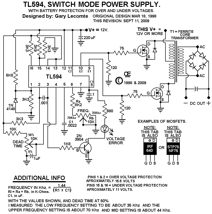
A 12 Volt Switching Power Supply
This circuit is designed for individuals needing to boost or drop a voltage. The output operates at high frequency but can be rectified and filtered to provide a DC output. When rectifying high frequencies, it is essential to utilize high-speed...
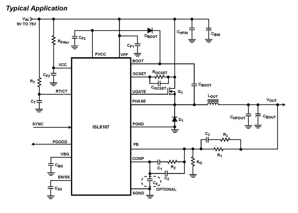
ISL8107 Single-Phase Pulse-Width Modulation (PWM) Controller with Wide (9V-75V) V
The ISL8107 is a single-phase, non-synchronous buck controller equipped with an integrated high-side MOSFET driver. It operates within an input voltage range of 9V to 75V. The internal reference voltage is 1.192V with a tolerance of ±1% across the industrial...
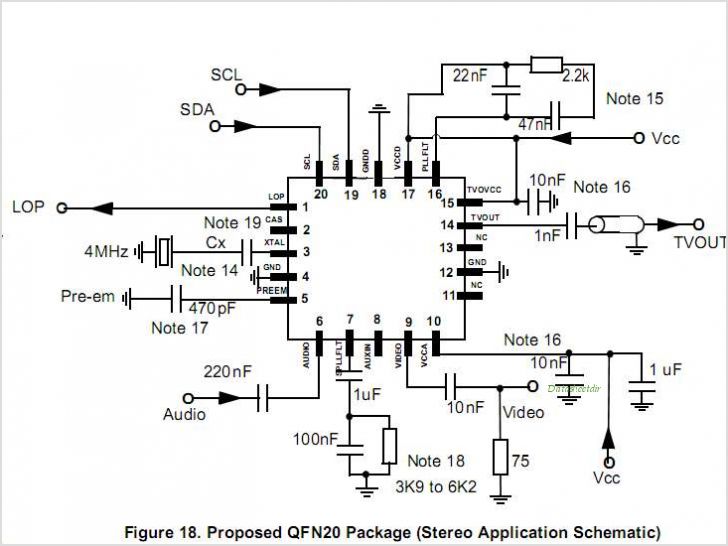
MC44BS373CA MC44BS373CA: PLL Tuned UHF And VHF Audio/Video High Integration Modulator
MC44BS374CA: PLL Tuned UHF and VHF Audio Video High Integration Modulator MC44BS374CA The MC44BS374CA Audio and Video Modulator is for use in VCRs, set-top boxes, and similar devices. By Freescale Semiconductor, Inc
The MC44BS374CA is a highly integrated audio and video...
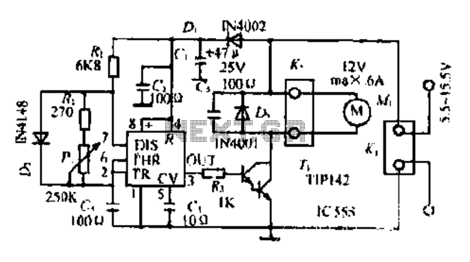
A DC motor PWM speed control circuit
Most governors utilize pulse width modulation (PWM) and pulse position modulation (PPM) in their circuits. The 555 timer is commonly used in these applications. The pulse width is typically fixed at 0.5 milliseconds, which is essential for the functioning of...
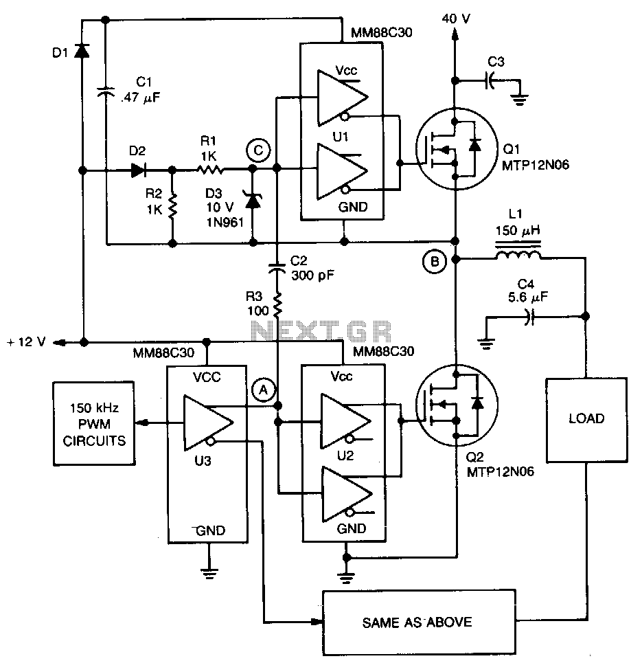
Pwm-servo-amplifier
A significant feature of the PWM servo amplifier is the removal of a pulse transformer. A 150 kHz pulse-width modulated signal is applied to U3, with its complementary outputs directed to identical circuits to drive the load. When point A...
250 to 5000 watts PWM DC/AC 220V Power Inverter
The schematic circuit design is for a 250-watt output inverter. To increase the power of the circuit, additional Q7 and Q8 transistors can be added in parallel; each pair contributes an additional 250 watts. For instance, to achieve 750 watts,...