


Simple Fuse Monitor Indicators
#fuse monitor
#LED indicator
#visual indication
#short circuit
#resistor
#safety circuit
#blown fuse detector
#simple circuit
#two-component circuit
#current limiter
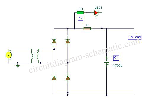
Description: This is a circuit diagram for a fuse monitor circuit indicator. This very simple circuit utilizes only two components: a single resistor and an LED. This circuit provides a visual indication when the fuse has blown. LED1 typically remains off, indicating a short circuit across the fuse, F1. It is important to note that the LED will only illuminate in a damaged condition, such as when there is a short circuit or shunt across the load. In this scenario, the current is reduced to a safe level by R1.
The fuse monitor circuit is designed to provide a straightforward method for detecting fuse failures within an electrical system. The circuit operates using minimal components, which enhances reliability and reduces the likelihood of component failure. The primary components involved in this circuit are an LED (LED1) and a current-limiting resistor (R1).
When the fuse (F1) is intact, the circuit remains in a normal operating state, and the LED remains off, indicating that the electrical path is complete and functioning correctly. However, if the fuse blows due to an overload or short circuit, the circuit configuration changes. The blown fuse creates a short circuit condition, allowing current to flow through the LED. As a result, LED1 illuminates, providing a clear visual indication that the fuse has failed and requires replacement.
The resistor (R1) plays a crucial role in this circuit by limiting the current flowing through the LED when it is illuminated. This current-limiting feature is essential to prevent damage to the LED due to excessive current. The value of R1 must be chosen carefully to ensure that it allows sufficient current to illuminate the LED while remaining within the safe operating limits of both the LED and the power supply.
This circuit can be implemented in various applications where fuse monitoring is critical, such as in power distribution panels, automotive systems, and consumer electronics. Its simplicity and effectiveness make it an ideal solution for providing immediate feedback on the status of fuses, enhancing safety and maintenance efficiency.This is a circuit diagram fuse monitor circuit indicators. This very simple circuit uses only two components, but only with a single resistor and LED this circuit provides visual indication when the fuse has blown. LED1 is usually dead, a short circuit by the fuse, F1. Please note that the LED will only illumininatet in damaged condition, ie with a short circuit or shunt the load.
In this case the current is reduced to a safe level by R1
The fuse monitor circuit is designed to provide a straightforward method for detecting fuse failures within an electrical system. The circuit operates using minimal components, which enhances reliability and reduces the likelihood of component failure. The primary components involved in this circuit are an LED (LED1) and a current-limiting resistor (R1).
When the fuse (F1) is intact, the circuit remains in a normal operating state, and the LED remains off, indicating that the electrical path is complete and functioning correctly. However, if the fuse blows due to an overload or short circuit, the circuit configuration changes. The blown fuse creates a short circuit condition, allowing current to flow through the LED. As a result, LED1 illuminates, providing a clear visual indication that the fuse has failed and requires replacement.
The resistor (R1) plays a crucial role in this circuit by limiting the current flowing through the LED when it is illuminated. This current-limiting feature is essential to prevent damage to the LED due to excessive current. The value of R1 must be chosen carefully to ensure that it allows sufficient current to illuminate the LED while remaining within the safe operating limits of both the LED and the power supply.
This circuit can be implemented in various applications where fuse monitoring is critical, such as in power distribution panels, automotive systems, and consumer electronics. Its simplicity and effectiveness make it an ideal solution for providing immediate feedback on the status of fuses, enhancing safety and maintenance efficiency.This is a circuit diagram fuse monitor circuit indicators. This very simple circuit uses only two components, but only with a single resistor and LED this circuit provides visual indication when the fuse has blown. LED1 is usually dead, a short circuit by the fuse, F1. Please note that the LED will only illumininatet in damaged condition, ie with a short circuit or shunt the load.
In this case the current is reduced to a safe level by R1
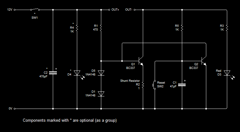
Latching Current Limiter
This entry describes a modification of a current limiter circuit originally created by Ron J. The original circuit functions as intended; however, a need arose to disconnect the load immediately after the maximum current threshold was reached, effectively creating a...

I burned out some resistors on the circuit board of my Roland
Some resistors on the circuit board of a Roland KC-300 amplifier have burned out and are so charred that their specifications cannot be determined. The resistors in question are R82, R83, R85, R92, and R93. Resistors R92 and R93 are...
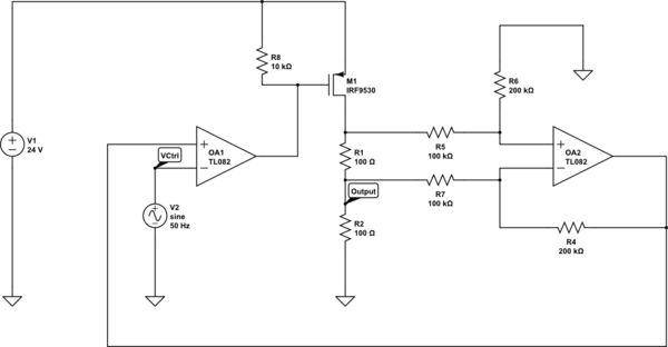
op amp Why does this current limiter circuit oscillate
Create a 0-25 mA current limiter using a control voltage input of 0-5 V to regulate the current through a resistive load (R2), which can vary between 0-200 ohms. The O2 operational amplifier (op-amp) functions as a differential amplifier with...

Safety Circuit Circuit
Due to the limited hold-on time of the delay circuits R1/C1 and R2/C2, both switches S1 and S2 must be activated simultaneously to energize the load.
The circuit in question involves a delay mechanism governed by the time constants associated with...
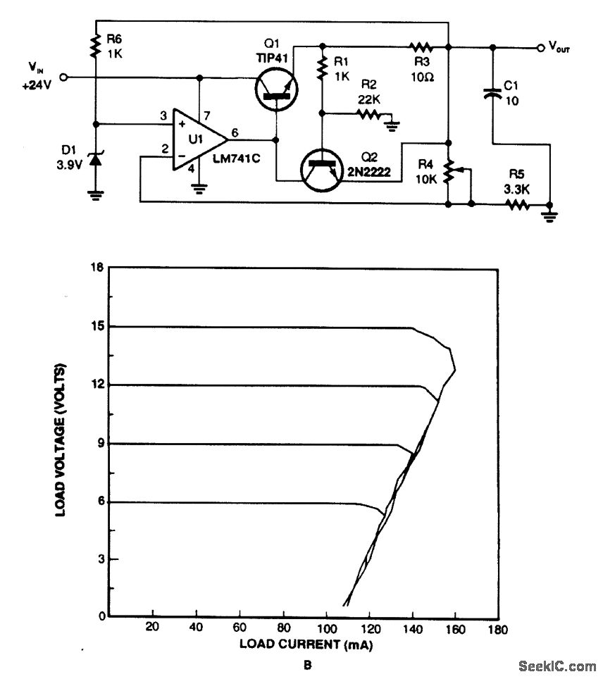
FOLDBACK CURRENT LIMITER
This regulator utilizes the voltage drop across resistor R3 to monitor current draw. When the current exceeds a certain threshold, Q2 is activated, which in turn disables Q1 and reduces the output voltage. Current limiting takes place when Q2 experiences...

An Add-on Current Limiter
This circuit allows for the establishment of a maximum output current limit from a power supply unit (PSU). It is particularly beneficial when initially powering a project or conducting a soak test. By imposing an upper current limit, protection is...
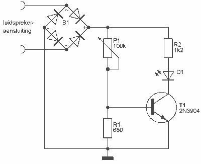
Audio Peak / Beat LED indicator
This indicator can be used, or see if your speakers can be damaged by the noise power. With P1 you can set the limit to which D1 LED lights. The pot is 100k here, you can even experiment with other...
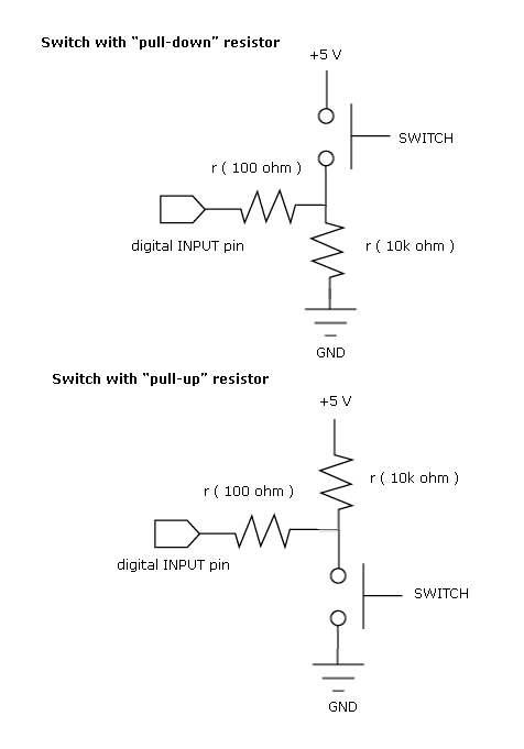
pull up and pull down resistor
Most beginners in digital electronics assume that a floating input represents a logic 0, which is a misconception. Floating inputs are in a neutral state and can represent either a logic 0 or a logic 1. This misunderstanding can lead...
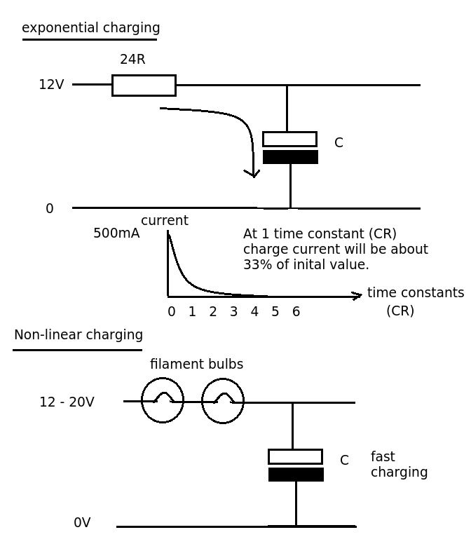
Transistor current limit circuit power handling
Designing a simple current limiter that charges a large 4.7mF capacitor with a charge current of approximately 500mA from a supply voltage of 10-20V. The dilemma is that there are existing MMBT2222A transistors available, which would be preferable to utilize...