


SL517 (electronic toy) audio RF or infrared decoder circuit
#SL517
#decoder
#CMOS
#RF
#infrared
#audio
#analog amplifier
#frequency divider
#bistable circuit
#driver
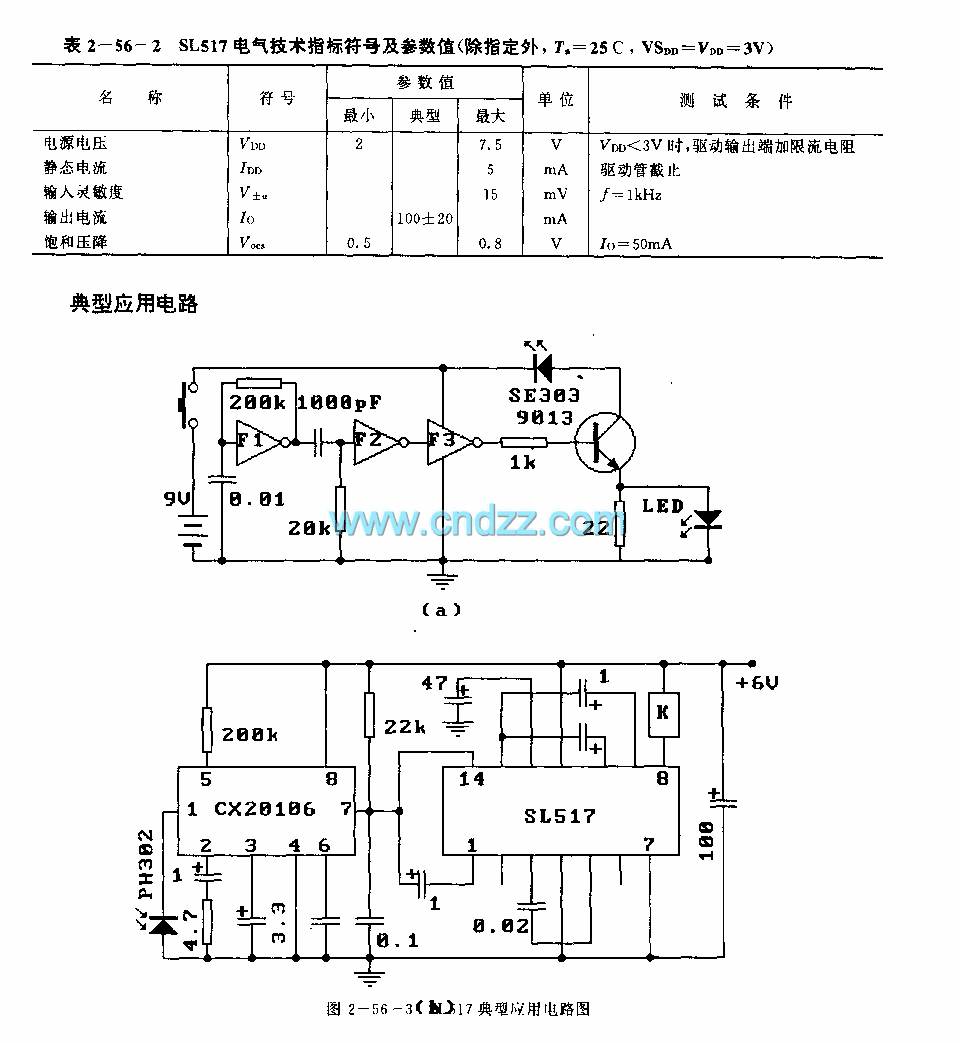
Description: The SL517 is designed as an audio, RF, or infrared decoder circuit suitable for electronic toy applications. The internal circuitry consists of an analog amplifier, a frequency divider, a bistable circuit, and a driver. It utilizes CMOS technology, has a wide power voltage range of 2-7.5V, and features low quiescent current.
The SL517 decoder circuit is engineered to decode audio, radio frequency (RF), or infrared signals, making it versatile for various electronic toy applications. The internal structure of the SL517 includes several critical components that work together to achieve efficient signal processing.
The analog amplifier serves to boost the strength of incoming signals, ensuring that even weak signals are adequately processed. Following this, the frequency divider plays a crucial role in down-converting the frequency of the received signal, making it easier to handle and decode. This is particularly important in applications where the incoming signal frequency may be significantly higher than the operational frequency of the subsequent circuitry.
The bistable circuit, often referred to as a flip-flop, is integral in maintaining the state of the output based on the input signals. This component allows the circuit to latch onto a particular state, which is essential for applications that require stable output based on transient inputs.
The driver component is responsible for controlling the output stage of the circuit, ensuring that it can effectively drive loads such as speakers or LEDs, which are common in toy applications.
Utilization of CMOS technology in the SL517 circuit design provides several advantages, including low power consumption and high noise immunity, which are essential for battery-operated devices like toys. The wide power voltage range of 2-7.5V allows for flexibility in power supply options, accommodating various battery configurations.
Overall, the SL517 decoder circuit is a robust solution for integrating audio, RF, or infrared decoding capabilities into electronic toys, providing a combination of performance, efficiency, and versatility.The SL517 is designed as the audio, RF or infrared decoder circuit that can be used in the electronic toy application. The internal circuit is composed of the analog amplifier, the frequency divider, the bistable circuit and the driver.
Features It uses the CMOS technology.The power voltage range is wide, the value is 2-7.5V.The quiescent current is small..
The SL517 decoder circuit is engineered to decode audio, radio frequency (RF), or infrared signals, making it versatile for various electronic toy applications. The internal structure of the SL517 includes several critical components that work together to achieve efficient signal processing.
The analog amplifier serves to boost the strength of incoming signals, ensuring that even weak signals are adequately processed. Following this, the frequency divider plays a crucial role in down-converting the frequency of the received signal, making it easier to handle and decode. This is particularly important in applications where the incoming signal frequency may be significantly higher than the operational frequency of the subsequent circuitry.
The bistable circuit, often referred to as a flip-flop, is integral in maintaining the state of the output based on the input signals. This component allows the circuit to latch onto a particular state, which is essential for applications that require stable output based on transient inputs.
The driver component is responsible for controlling the output stage of the circuit, ensuring that it can effectively drive loads such as speakers or LEDs, which are common in toy applications.
Utilization of CMOS technology in the SL517 circuit design provides several advantages, including low power consumption and high noise immunity, which are essential for battery-operated devices like toys. The wide power voltage range of 2-7.5V allows for flexibility in power supply options, accommodating various battery configurations.
Overall, the SL517 decoder circuit is a robust solution for integrating audio, RF, or infrared decoding capabilities into electronic toys, providing a combination of performance, efficiency, and versatility.The SL517 is designed as the audio, RF or infrared decoder circuit that can be used in the electronic toy application. The internal circuit is composed of the analog amplifier, the frequency divider, the bistable circuit and the driver.
Features It uses the CMOS technology.The power voltage range is wide, the value is 2-7.5V.The quiescent current is small..
SimpleTimer with Musical Alarm
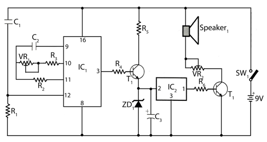
The circuit timer with a musical alarm utilizes a well-known CMOS oscillator/divider integrated circuit (IC1). Although this circuit operates at 9V, its standby current drain is minimal. The time delay of the timer circuit can be adjusted by modifying the...
Repeating Interval Timer 2
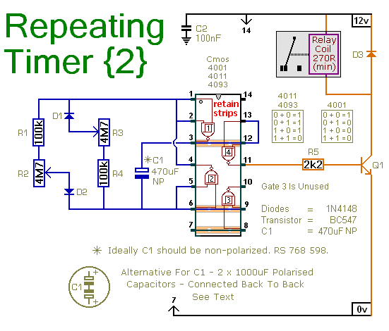
This is a simpler repeating timer circuit. It uses just one CMOS IC wired as an asymmetric oscillator. The length of time the relay remains energized and the length of time it remains de-energized are set independently.
The repeating timer circuit...
Infrared Heart Pulse Monitor
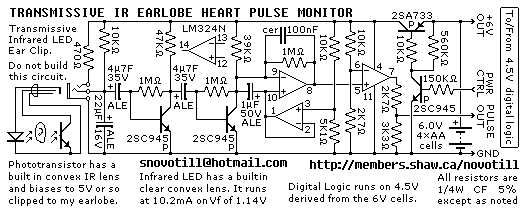
Senses heart pulse by means of an infrared earlobe clip. Reverse engineered circuit diagram of heart pulse sensor circuit board out of a treadmill. Notice that the output is level shifted for use by CMOS logic running on 4.5V regulated...
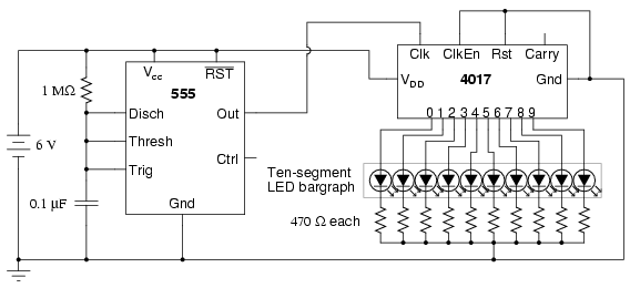
LED sequencer
The model 4017 integrated circuit is a CMOS counter with ten output terminals. At any given time, one of these ten terminals will be in a "high" state, while all others remain "low," resulting in a "one-of-ten" output sequence. When...
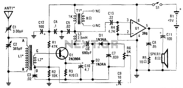
Reflex Radio Receiver
The RF signal is transmitted from the antenna through CI to a tuned circuit consisting of LI and C2. One end of L2 delivers the RF signal to the base of Q1 for amplification, while the other end connects to...
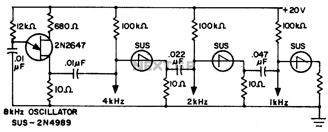
Frequency divider chain
The sawtooth output from each stage is one half the frequency of the preceding stage.
The described circuit features a multi-stage sawtooth waveform generator, where each stage produces an output with a frequency that is half of the frequency generated by...
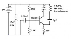
RF-Radio Frequency 6
This circuit is designed to attenuate signal frequency, with a customizable range from 1 to 40 dB. For UHF band usage, it should be enclosed within a shielded frame, and capacitors C1 to C3 should be appropriately selected. The connection...
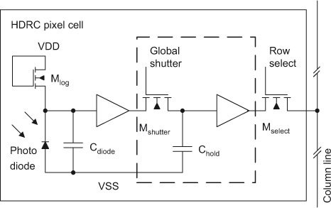
High dynamic range CMOS (HDRC) imagers for safety systems
The initial section of this document outlines the high dynamic range CMOS (HDRC) imager, a specialized type of CMOS image sensor characterized by its logarithmic response. The significant capabilities of high dynamic range (HDR) image acquisition are explained through mathematical...

Cmos Piezo Driver Circuit
A CMOS gate and transistor buffer can be used as an effective driver for a piezoelectric transducer.
The use of a CMOS gate combined with a transistor buffer offers a robust solution for driving piezoelectric transducers. CMOS technology, known for its...