


Sleeping-Aids
#sleep aid
#square wave generator
#timer
#alternate mode
#brain environment
#Geo-magnetic-fields
#IC2C
#IC2D
#sound sleep
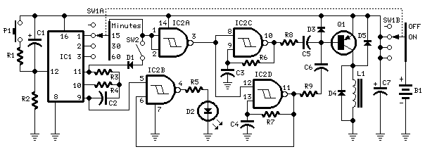
Description: The circuit generates geomagnetic fields that allow for their perception, creating an ideal environment for sound sleep. When SW2 is open (Alternate mode operation), the device operates for a pre-set duration and then pauses for the same amount of time, repeating this cycle indefinitely. IC2C and IC2D generate two square waves at approximately 1.2 Hz and 5 Hz, respectively. These waveforms are converted into 60 µs pulses at the same frequencies using capacitors C5 and C6, which are mixed at the base of transistor Q1. This transistor drives the radiator coil with a series of scalar pulses, each 60 µs in length and 9V in amplitude. IC1, IC2A, and IC2B form the timer section of the circuit. Capacitor C1 and resistor R2 provide an auto-reset function for IC1 upon switch-on. The internal oscillator of IC1 controls a 14-stage ripple counter, and after approximately 15 minutes, output pin 1 goes high, causing pin 3 of IC2A to go low and stopping the oscillation of IC2C and IC2D. In Stop mode operation (when SW2 is closed), the first time output pin 1 of IC1 goes high, the internal oscillator of IC1 is disabled via diode D1, keeping the circuit off until a reset pulse is applied to pin 12 through potentiometer P1 or when the entire device is switched off and restarted. The inductor L1 is created by winding 600 turns of 0.2 mm enameled wire around a 6 mm diameter, 40 mm long steel bolt, secured with insulating tape.
The circuit design focuses on generating specific frequencies that mimic natural geomagnetic fields, which are believed to promote relaxation and improve sleep quality. The dual frequency generation, achieved through the use of IC2C and IC2D, allows for the modulation of the magnetic field, simulating the natural variations found in geomagnetic environments. The square wave outputs are crucial for maintaining the intended pulse duration, which is finely tuned to 60 µs to ensure effective interaction with the human brain.
The timer section, composed of IC1, IC2A, and IC2B, is essential for controlling the operational cycles of the device. The auto-reset feature provided by C1 and R2 ensures that the circuit can be reliably restarted each time it is powered on, maintaining consistent performance. The use of a 14-stage ripple counter allows for precise timing control, facilitating the transition between active and pause states of the circuit.
The implementation of the Stop mode via SW2 provides flexibility in operation, allowing users to halt the device when desired. The disabling of the internal oscillator through D1 upon the first high signal from pin 1 of IC1 ensures that the device does not inadvertently reactivate without user intervention, adding a layer of safety and control.
The construction of inductor L1 is critical, as the specific winding technique and choice of materials directly impact the performance of the radiator coil. The choice of a steel bolt as a core material enhances the magnetic field generation, while the specified number of turns optimizes the inductance for the desired output characteristics. Proper insulation of the winding is necessary to prevent short circuits and ensure the longevity of the component. Overall, this circuit exemplifies a thoughtful integration of various electronic components to achieve a specific therapeutic effect.The circuit generates this type of Geo-magnetic-fields and lets us perceive them: in this manner our brain is surrounded by an ideal environment for a sound sleep. With SW2 opened (Alternate mode operation) the device operates for the pre-set time, then pauses for the same amount of time: this cycle repeats indefinitely.
IC2C and IC2D generate two square waves at about 1. 2 and 5 Hz respectively. These wave-forms are converted into 60 µS pulses at the same frequencies by means of C5 & C6 and mixed at Q1`s Base. This transistor drives the Radiator coil with a scalar series of pulses of 60 µS length and 9V amplitude.
IC1, IC2A & IC2B form the timer section. C1 & R2 provide auto-reset of IC1 at switch-on. The internal oscillator of IC1 drives the 14 stage ripple counter and, after about 15 minutes, output pin 1 goes high. Pin 3 of IC2A goes low and stops IC2C & IC2D oscillation. If SW2 is closed (Stop mode operation), the first time output pin 1 of IC1 goes high, the internal oscillator of the IC is disabled by means of D1.
Therefore the circuit remains off until a reset pulse is applied to pin 12 by means of P1 or when the whole device is switched-off and then restarted. L1 is obtained by winding randomly 600 turns of 0. 2 mm. enameled wire on a 6 mm. diameter, 40 mm. long, steel bolt. Secure the winding with insulating tape.
The circuit design focuses on generating specific frequencies that mimic natural geomagnetic fields, which are believed to promote relaxation and improve sleep quality. The dual frequency generation, achieved through the use of IC2C and IC2D, allows for the modulation of the magnetic field, simulating the natural variations found in geomagnetic environments. The square wave outputs are crucial for maintaining the intended pulse duration, which is finely tuned to 60 µs to ensure effective interaction with the human brain.
The timer section, composed of IC1, IC2A, and IC2B, is essential for controlling the operational cycles of the device. The auto-reset feature provided by C1 and R2 ensures that the circuit can be reliably restarted each time it is powered on, maintaining consistent performance. The use of a 14-stage ripple counter allows for precise timing control, facilitating the transition between active and pause states of the circuit.
The implementation of the Stop mode via SW2 provides flexibility in operation, allowing users to halt the device when desired. The disabling of the internal oscillator through D1 upon the first high signal from pin 1 of IC1 ensures that the device does not inadvertently reactivate without user intervention, adding a layer of safety and control.
The construction of inductor L1 is critical, as the specific winding technique and choice of materials directly impact the performance of the radiator coil. The choice of a steel bolt as a core material enhances the magnetic field generation, while the specified number of turns optimizes the inductance for the desired output characteristics. Proper insulation of the winding is necessary to prevent short circuits and ensure the longevity of the component. Overall, this circuit exemplifies a thoughtful integration of various electronic components to achieve a specific therapeutic effect.The circuit generates this type of Geo-magnetic-fields and lets us perceive them: in this manner our brain is surrounded by an ideal environment for a sound sleep. With SW2 opened (Alternate mode operation) the device operates for the pre-set time, then pauses for the same amount of time: this cycle repeats indefinitely.
IC2C and IC2D generate two square waves at about 1. 2 and 5 Hz respectively. These wave-forms are converted into 60 µS pulses at the same frequencies by means of C5 & C6 and mixed at Q1`s Base. This transistor drives the Radiator coil with a scalar series of pulses of 60 µS length and 9V amplitude.
IC1, IC2A & IC2B form the timer section. C1 & R2 provide auto-reset of IC1 at switch-on. The internal oscillator of IC1 drives the 14 stage ripple counter and, after about 15 minutes, output pin 1 goes high. Pin 3 of IC2A goes low and stops IC2C & IC2D oscillation. If SW2 is closed (Stop mode operation), the first time output pin 1 of IC1 goes high, the internal oscillator of the IC is disabled by means of D1.
Therefore the circuit remains off until a reset pulse is applied to pin 12 by means of P1 or when the whole device is switched-off and then restarted. L1 is obtained by winding randomly 600 turns of 0. 2 mm. enameled wire on a 6 mm. diameter, 40 mm. long, steel bolt. Secure the winding with insulating tape.
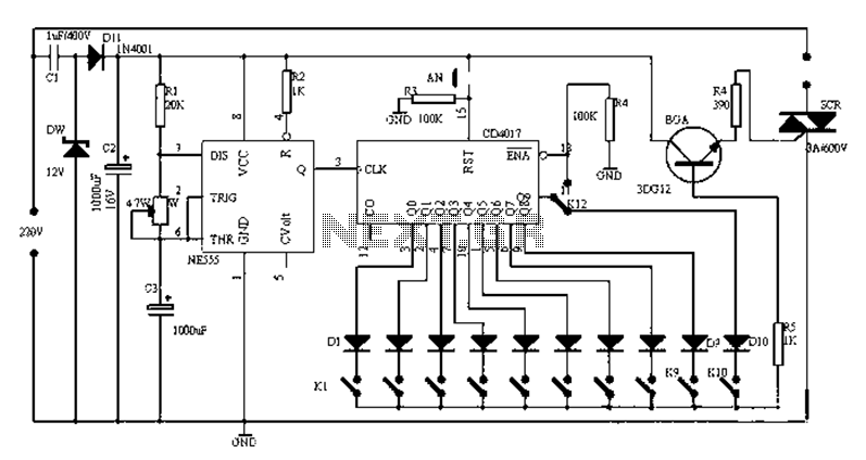
Universal electronic timer circuit diagram
Figure 1-1 illustrates a general-purpose timer capable of timing intervals ranging from 5 minutes to 18 hours. The timing cycle can be adjusted to span from 5 minutes to 20 hours, with a maximum control time of 18 hours. The...
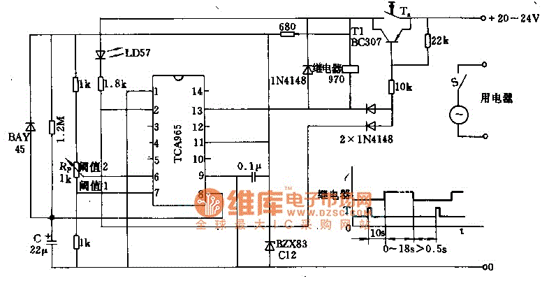
Timer circuit with 106 fixed preset time
The foot 13 between valve value 1 and valve value 2 will draw the transistor base current. If the relay releases, after a recovery time of 0.5 seconds, pressing the key will initiate the switching process again. The timer is...
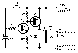
headlights timer
This device is a simple timer that keeps the headlights of a vehicle illuminated for approximately 1 minute and 30 seconds. This feature is particularly useful when accessing dark areas, eliminating the need to return to manually switch off the...
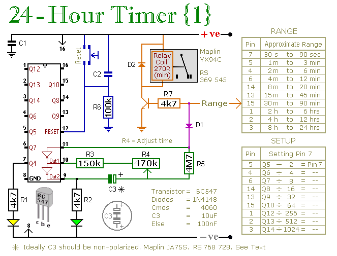
24 Hour Timer
These two circuits are multi-range timers that offer periods of up to 24 hours and beyond. Both circuits are fundamentally similar, with the key distinction being that Version 1 energizes the relay when the time expires, while Version 2 de-energizes...
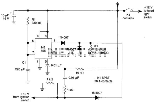
Automatic Turn-Off Control For Automobiles Circuit
When the ignition switch is activated, relay K1 receives continuous power, allowing the headlights to be turned on. When the ignition is turned off, timer IC1 is activated, maintaining its power for a duration determined by resistor R1 and capacitor...

Head light timer circuit
This circuit is a compact timer designed to keep the headlights of a car illuminated for approximately 1.5 minutes before automatically turning them off. By integrating this circuit into a vehicle, users can access dark areas without the need to...
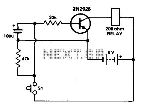
Simple timer
Press SI. The 100 µF electrolytic capacitor rapidly charges up from approximately 0 V. The transistor becomes forward biased, allowing collector current to flow and operate the relay. When SI is released, the capacitor discharges through the 33 K resistor...
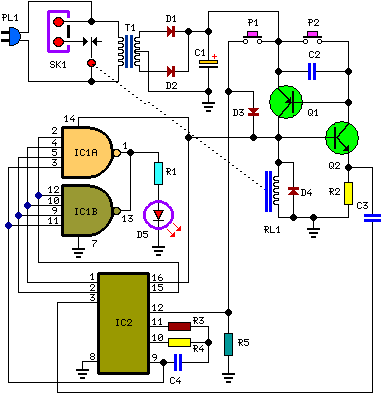
A Bedside Lamp Timer Circuit Schematic
The purpose of this circuit is to power a lamp or other appliance for a specified duration (30 minutes in this case) and then automatically turn it off. This feature is particularly useful for reading in bed at night, as...
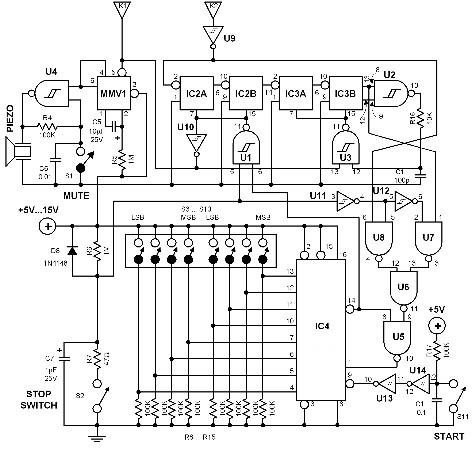
universal timer
The time interval of this circuit can be varied digitally through the DIP switches. The time code must be set in BCD form. A 120 Hz signal generated by doubling the line frequency is used as the time reference. This...