


Splicing a Minolta/Sony flash cable
#flash cable
#PC synch cord
#extension cable
#connector
#isolation circuit
#high voltage
#photography
#electronics modification
Description: A PC sync cord can be created from an extension cable by incorporating a connector and attaching different plugs on the opposite end. This setup includes an isolation circuit housed in a CF case, which ensures that high voltage does not reach the camera or flash. It is important to note that the orange-orange-red banded resistor next to the white wire is not utilized and is merely present to avoid confusion. The main light sources, such as the KM5600, KM3600, or their Sony equivalents, can operate in TTL or manual mode, but not in HSS or WL modes. The KM 5D or Sony A100 can function in any mode except HSS or WL. The KM 7D can operate in manual or TTL mode, excluding HSS or WL. Therefore, none of the equipment should be set to HSS or WL. The inexpensive add-on flash does not pre-flash like the main light and will only activate during the actual exposure. The KM or Sony flash can operate in TTL or manual mode as previously configured. The inexpensive flash can be effectively used to illuminate the background or serve as a hair light, as it does not pre-flash, meaning the camera will not adjust for its light output, providing additional illumination.
A PC sync cord is a vital accessory for synchronizing the flash with the camera shutter. The proposed design utilizes an extension cable, allowing for flexibility in length and adaptability. The incorporation of a connector enables easy attachment to various camera models and flash units. The isolation circuit is crucial in this configuration, as it protects sensitive camera electronics from high voltage spikes that could occur during flash operation. This circuit is typically composed of opto-isolators or transformers, which provide electrical isolation while allowing the necessary synchronization signals to pass through.
The configuration of the main light sources is essential for achieving desired photographic results. The KM5600 and KM3600 lights, along with their Sony counterparts, are versatile in their operation modes, allowing for TTL (Through The Lens) metering or manual control. However, it is critical to ensure that these devices are not set to HSS (High-Speed Sync) or WL (Wireless) modes, as these settings can interfere with the proper functioning of the sync cord and the resulting exposure.
The use of an inexpensive add-on flash provides additional lighting options for the photographer. This flash unit is designed to fire only during the exposure, making it suitable for background lighting or as a hair light. Since it does not pre-flash, it offers uncontrolled light output that can enhance the overall image without the camera needing to compensate for its illumination. This characteristic allows for creative lighting techniques, contributing to the overall effectiveness of the photographic setup.
In summary, the proposed PC sync cord design provides an effective solution for synchronizing flash units with cameras while ensuring safety and versatility in lighting options. The careful consideration of equipment modes and the role of each flash unit enhances the photographer's ability to achieve the desired aesthetic in their images.Create a PC synch cord off of the extension cable by putting in a connector and having different plugs on the opposite end. So if I read this correctly, you could create a PC synch cord off of the extension cable by putting in a connector and having different plugs on the opposite end.
As you can see below, the isolation circuit is mounted in a CF case. It makes sure you will not put high voltage into your camera or flash. Note: Ignore the `orange-orange-red` banded resistor next to the white wire. I did not use it and is is just sitting there (to confuse people, lol). The main light (KM5600 or KM3600, or the Sony versions) can be in TTL or manual mode but not HSS or WL. The KM 5D or Sony A100 is in any mode except HSS or WL mode. The KM 7D can be in manual or TTL mode, but not HSS or WL. In other words, no equipment can be in HSS or WL mode. The cheap add-on flash will not pre-flash like the main light, it will only fire during the actual exposure flash.
The KM or Sony flash will TTL or do manual just as set beforehand. A good use for the cheap flash is to light up the background or as a hair light. It does not pre-flash and so the camera will not know how to account for it`s light output. It will be just `extra` light.
A PC sync cord is a vital accessory for synchronizing the flash with the camera shutter. The proposed design utilizes an extension cable, allowing for flexibility in length and adaptability. The incorporation of a connector enables easy attachment to various camera models and flash units. The isolation circuit is crucial in this configuration, as it protects sensitive camera electronics from high voltage spikes that could occur during flash operation. This circuit is typically composed of opto-isolators or transformers, which provide electrical isolation while allowing the necessary synchronization signals to pass through.
The configuration of the main light sources is essential for achieving desired photographic results. The KM5600 and KM3600 lights, along with their Sony counterparts, are versatile in their operation modes, allowing for TTL (Through The Lens) metering or manual control. However, it is critical to ensure that these devices are not set to HSS (High-Speed Sync) or WL (Wireless) modes, as these settings can interfere with the proper functioning of the sync cord and the resulting exposure.
The use of an inexpensive add-on flash provides additional lighting options for the photographer. This flash unit is designed to fire only during the exposure, making it suitable for background lighting or as a hair light. Since it does not pre-flash, it offers uncontrolled light output that can enhance the overall image without the camera needing to compensate for its illumination. This characteristic allows for creative lighting techniques, contributing to the overall effectiveness of the photographic setup.
In summary, the proposed PC sync cord design provides an effective solution for synchronizing flash units with cameras while ensuring safety and versatility in lighting options. The careful consideration of equipment modes and the role of each flash unit enhances the photographer's ability to achieve the desired aesthetic in their images.Create a PC synch cord off of the extension cable by putting in a connector and having different plugs on the opposite end. So if I read this correctly, you could create a PC synch cord off of the extension cable by putting in a connector and having different plugs on the opposite end.
As you can see below, the isolation circuit is mounted in a CF case. It makes sure you will not put high voltage into your camera or flash. Note: Ignore the `orange-orange-red` banded resistor next to the white wire. I did not use it and is is just sitting there (to confuse people, lol). The main light (KM5600 or KM3600, or the Sony versions) can be in TTL or manual mode but not HSS or WL. The KM 5D or Sony A100 is in any mode except HSS or WL mode. The KM 7D can be in manual or TTL mode, but not HSS or WL. In other words, no equipment can be in HSS or WL mode. The cheap add-on flash will not pre-flash like the main light, it will only fire during the actual exposure flash.
The KM or Sony flash will TTL or do manual just as set beforehand. A good use for the cheap flash is to light up the background or as a hair light. It does not pre-flash and so the camera will not know how to account for it`s light output. It will be just `extra` light.
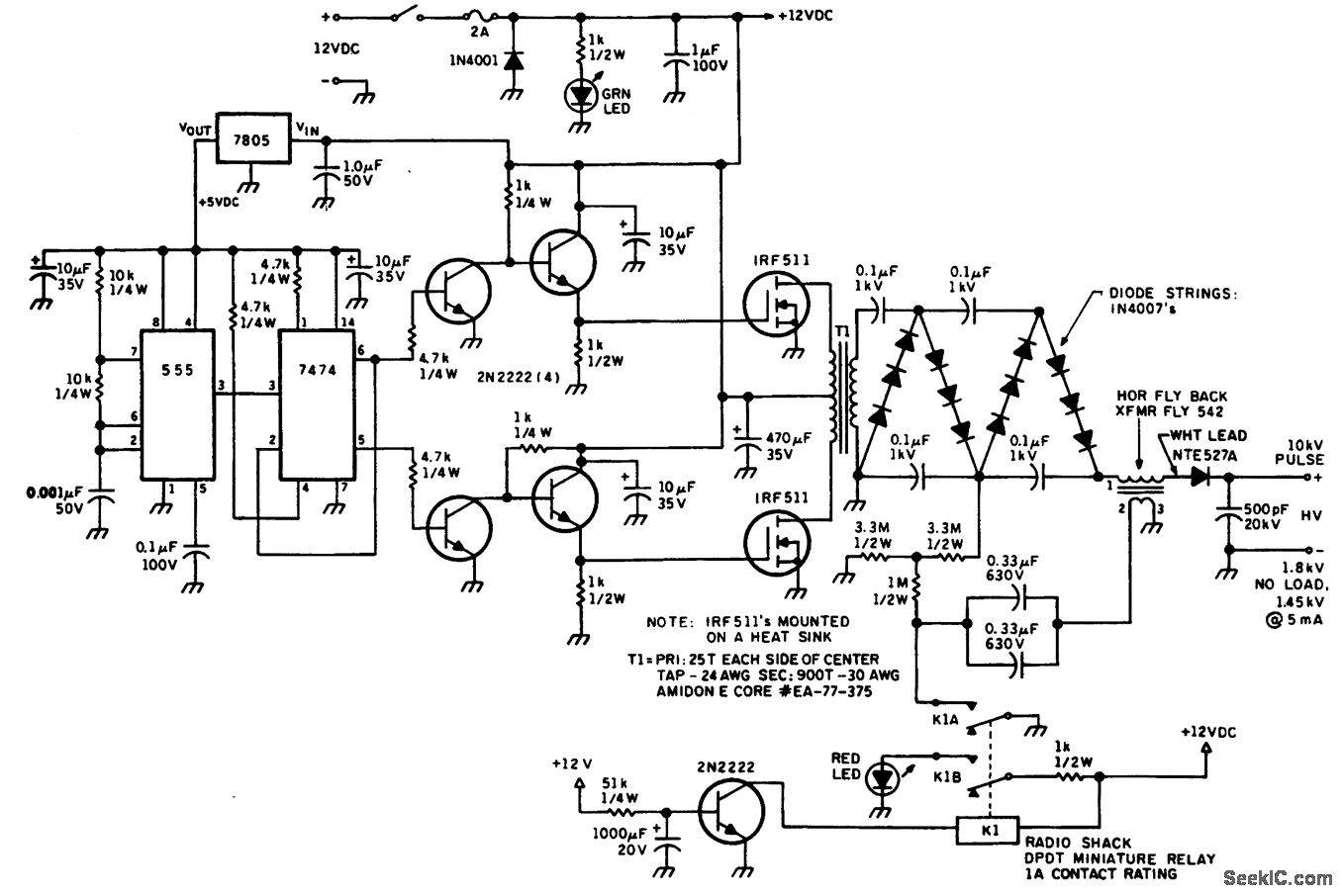
HELIUM NEON LASER PS WITH HV PULSE IGNITION
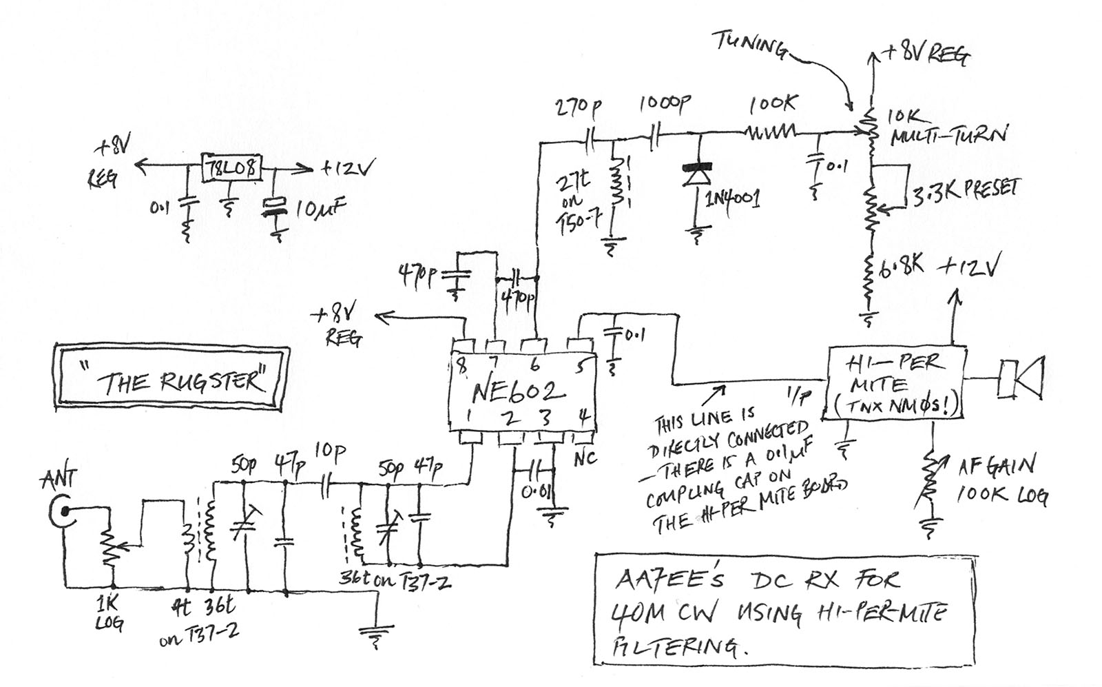
The helium-neon laser requires two voltages: one in the range of 10 kV to initiate the laser, which is turned off once the discharge begins, and a lower-voltage power supply to sustain the discharge. The circuit diagram illustrates a method...
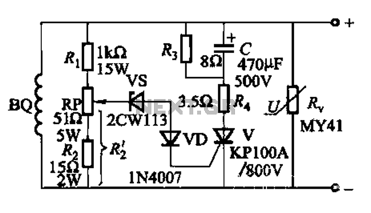
High voltage generator excitation set overvoltage protection circuit
The DC voltage for the generator field winding is supplied by a three-phase thyristor rectifier. In instances of incorrect operation, phase misalignment, or system failure, the rectifier may generate hazardous conditions, leading to over-voltage insulation issues on the DC side...
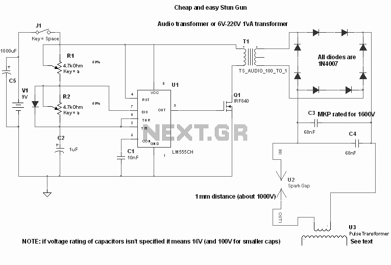
High Voltage Stun Gun
High Voltage Stun Gun Disclaimer: This device is not a toy. It should not be misused. The creator does not accept any responsibility for damages caused to others or oneself with this device. If one intends to build it, they...
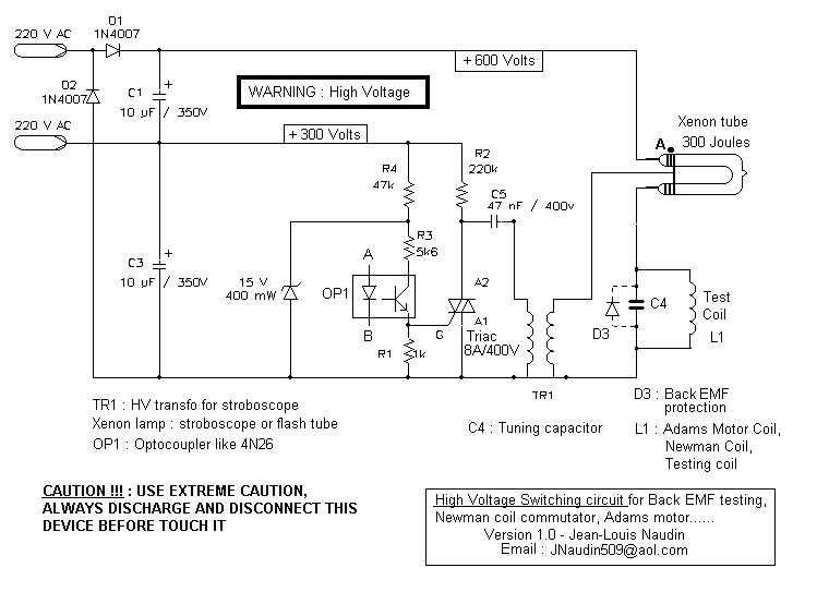
High Voltage Switching for Energy Recovery
This is a High Voltage switching device for driving coils and which have big impedance when it is switched off. It can be used in Back-EMF energy recovery tests, Newman coils electronic commutator. This device is driven by an opto-coupler...
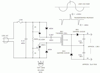
12KV High Voltage Generator
The hobby circuit described utilizes a unique method to generate approximately 12,000 volts with a current of about 5 microamperes. It employs two silicon-controlled rectifiers (SCRs) that form two pulse generator circuits. These SCRs discharge a 0.047 microfarad, 400-volt capacitor...

High voltage stable power supply
The schematic diagram originates from a circuit designed for a stable power supply ranging from -100V to -1000V. For further details, refer to the page that explains the circuit diagram associated with this power supply. This stable power supply serves...
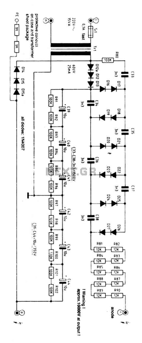
High Voltage Power Supply 10kV
Exercise caution with this power supply as it operates on 220V mains and has an output voltage of 10KV. Characteristics: Supply: 220V AC 50Hz mains, Power: 15 Watts, Ignition Voltage: 8KV.
The power supply operates on a standard 220V AC input...
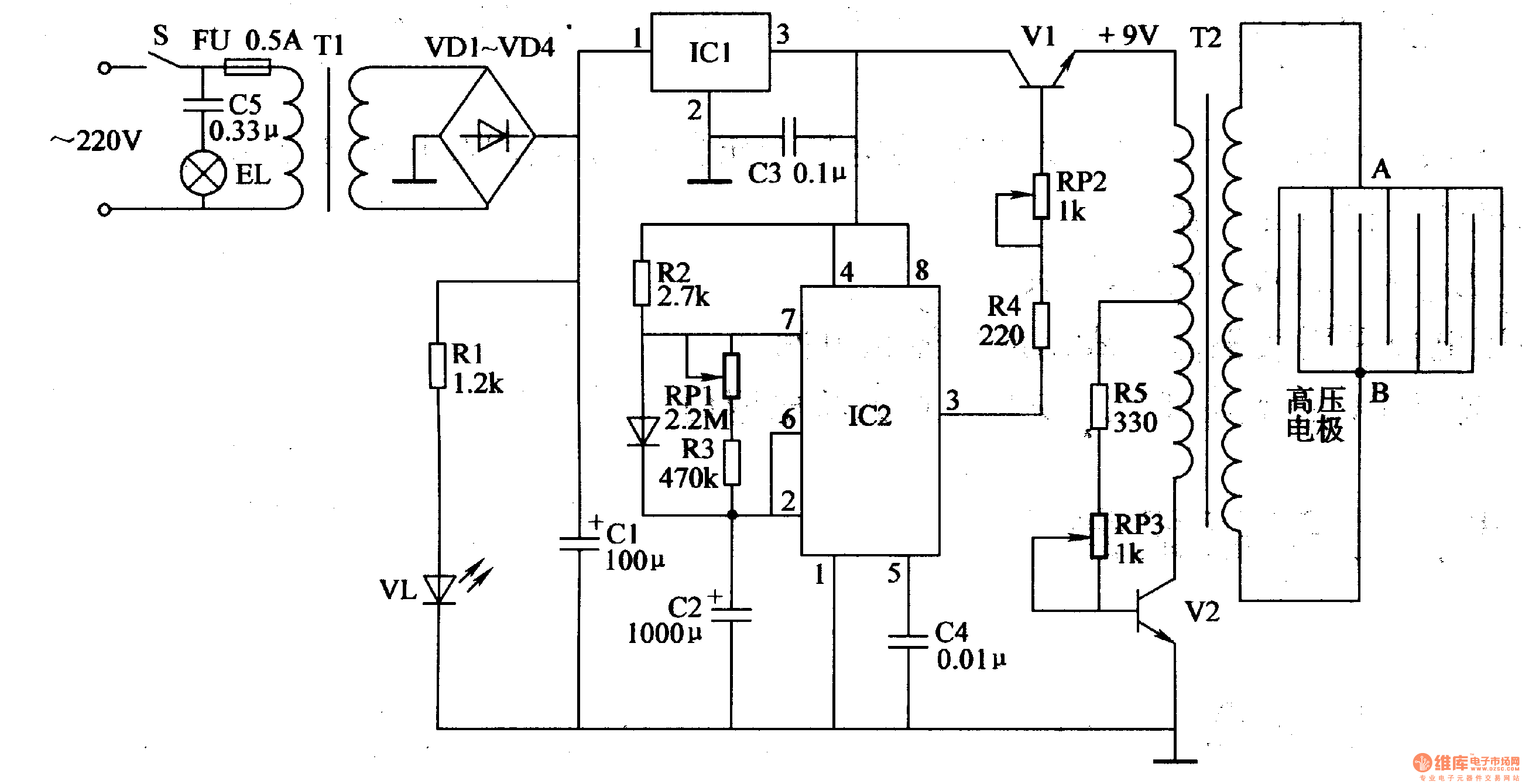
Electronic Pest Killing Lamp
Working Principle: The circuit, as illustrated in figure 4-187, is composed of three main components: the power circuit, the pulse oscillator, and the high voltage generator. The power circuit includes components S, FU, TI, VD1-VD4, C1, C3, IC1, R1, and...
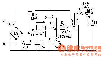
High Voltage Generator
This high voltage generator is capable of producing a stable high voltage exceeding 8kV. The circuit design is straightforward, ensuring stability and reliability. It consists of a step-down rectifier, a voltage regulator circuit, an 18kHz multivibrator-type oscillator, and a booster...