


Stimulus-isolator

Description: This stimulus isolator utilizes a photo-SCR and a toroidal transformer to shape pulses of up to 200 V at 200 pA.
The stimulus isolator is designed to provide electrical isolation between the stimulus source and the load, ensuring that the high voltage pulses do not interfere with sensitive components within the circuit. The use of a photo-SCR (silicon-controlled rectifier) allows for precise control of the pulse shaping, enabling the generation of high-voltage outputs while maintaining low current levels.
The toroidal transformer plays a critical role in this circuit by efficiently coupling the input signal to the output while minimizing electromagnetic interference. The toroidal design is beneficial due to its compact size and reduced magnetic leakage, which enhances the overall performance of the isolator.
In operation, the input signal triggers the photo-SCR, which then allows the current to flow through the toroidal transformer. The transformer shapes the pulse according to the design specifications, delivering output pulses that can reach voltages of up to 200 V. The low current rating of 200 pA ensures that the circuit can interface safely with sensitive electronic components without causing damage or distortion.
This configuration is particularly useful in applications that require high-voltage stimulus signals, such as in electrophysiological experiments, while providing the necessary isolation to protect both the signal source and the receiving equipment. The careful selection of components, including the photo-SCR and toroidal transformer, contributes to the reliability and efficiency of the stimulus isolator circuit.This stimulus isolator uses a photo-SCR and a toroid for shaping pulses of up to 200 V at 200 p.A. The circuit.
The stimulus isolator is designed to provide electrical isolation between the stimulus source and the load, ensuring that the high voltage pulses do not interfere with sensitive components within the circuit. The use of a photo-SCR (silicon-controlled rectifier) allows for precise control of the pulse shaping, enabling the generation of high-voltage outputs while maintaining low current levels.
The toroidal transformer plays a critical role in this circuit by efficiently coupling the input signal to the output while minimizing electromagnetic interference. The toroidal design is beneficial due to its compact size and reduced magnetic leakage, which enhances the overall performance of the isolator.
In operation, the input signal triggers the photo-SCR, which then allows the current to flow through the toroidal transformer. The transformer shapes the pulse according to the design specifications, delivering output pulses that can reach voltages of up to 200 V. The low current rating of 200 pA ensures that the circuit can interface safely with sensitive electronic components without causing damage or distortion.
This configuration is particularly useful in applications that require high-voltage stimulus signals, such as in electrophysiological experiments, while providing the necessary isolation to protect both the signal source and the receiving equipment. The careful selection of components, including the photo-SCR and toroidal transformer, contributes to the reliability and efficiency of the stimulus isolator circuit.This stimulus isolator uses a photo-SCR and a toroid for shaping pulses of up to 200 V at 200 p.A. The circuit.
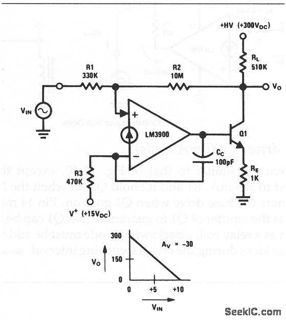
Norton high voltage inverting amplifier
This circuit is an inverting amplifier with an output voltage swing from approximately 0 to +300 V. Any transistor can be utilized for Q1, as long as the breakdown voltage exceeds 300 V (since the full high voltage will be...
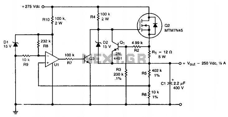
HV regulator with foldback current limiting
A TMOS MTM7N45 (Q2) is utilized as a series pass element in a linear high voltage supply that accepts +275 V unregulated and produces 250 V regulated with foldback current limiting. A 15 V zener diode (D1) provides the DC...
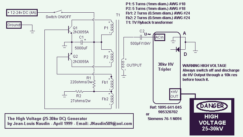
The 25-30kV DC Generator
This High Voltage power supply is able to generate up to 25-30kV DC Output from a 12-24v DC input. With a fully adjustable DC input power supply (0-24V/4A), it is possible to adjust the HV output between 5 to 30kV....
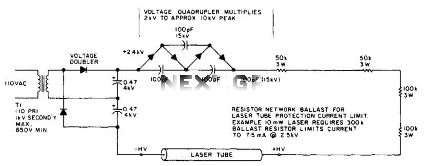
Laser Power Supply And Starting Circuit Circuit
This circuit delivers a peak voltage of 10 kV, while limiting the current to 7.5 mA at 2 kV. The resistors included in the design serve the purpose of ballasting. Additionally, the starting circuit is unable to sustain the 10...
High Voltage Converter Circuit
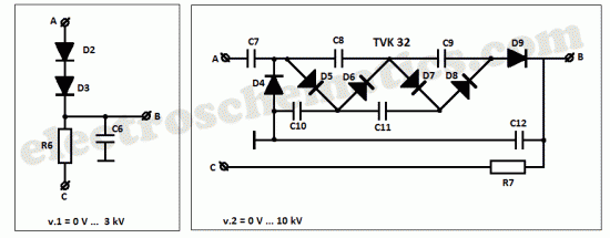
This high voltage converter circuit begins with a 30-volt power supply and is capable of delivering output voltages ranging from 0 to 3 kV for version 1, or from 0 to 10 kV for version 2.
The high voltage converter circuit...
MicroFlash Schematic
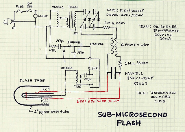
The two resistors serve dual purposes. Firstly, they limit the current to a lower value in case of accidental contact with the circuit. Secondly, when the flash is activated, the main capacitor behaves like a short circuit to the power...
How to calculate toroidcoils
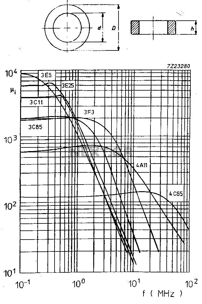
This side will explain how to calculate toroid coils. I have made toroid tests with different number of turns and measured the inductance. Formula: L (nH) = N² * AL. Where: L = inductance in nanohenrys. N = number of...
Hv Power Supply With 9 To 15Vdc Input Circuit
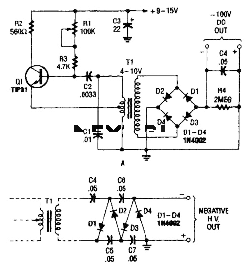
The combination of a Hartley oscillator and a step-up transformer can generate significant negative high voltage, particularly when the voltage output of the transformer is multiplied by the circuit in B.
The Hartley oscillator is a type of LC oscillator that...
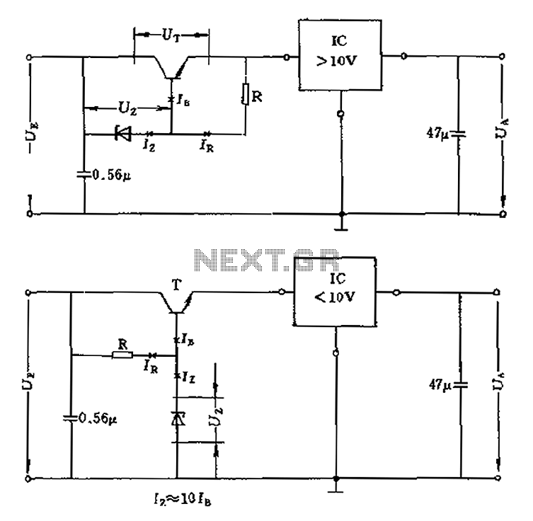
High operating voltage regulator circuit diagram
The voltage equation Ue = Ut + Ur + Ua indicates that the transistor voltage Ut will determine the maximum output voltage Ua. Additionally, Ur must be 2V. The voltage regulator's voltage value depends on the selection of Uz. In...