


TDA8358J application circuit
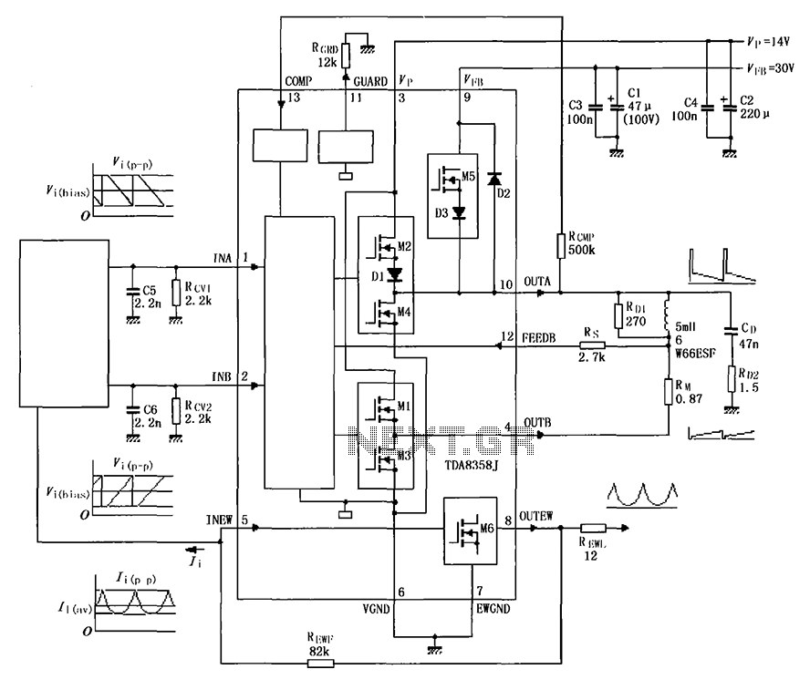
Description: The TDA8358J application circuit is designed for television signal processing. The input signals are connected to the TDA8358J at pins 1 and 2, where pin 1 receives a positive sawtooth voltage input and pin 2 receives a negative sawtooth voltage input. The internal circuitry includes a differential amplifier and a push-pull power amplifier, which generate an output that drives the deflection coil connected to pins 10 and 4. A resistor (RM) is placed in series with the deflection coil to provide feedback voltage through pin 12 (Rs). This configuration enhances the linear sawtooth output and expands the dynamic range of the sawtooth waveform. The output current can be adjusted by modifying the resistance values of RM and RCV, with a maximum output current limit of 3.2 A peak-to-peak.
The TDA8358J is a highly integrated circuit designed for television applications, particularly for horizontal and vertical deflection control. In this circuit, the positive and negative sawtooth voltages applied to pins 1 and 2, respectively, are critical for generating the necessary deflection signals. The differential amplifier within the TDA8358J processes these input signals, allowing for precise control over the output waveform.
The push-pull power amplifier configuration is essential for driving the deflection coil, which is responsible for the movement of the electron beam in CRT televisions. The output from the power amplifier is applied to the deflection coil connected to pins 10 and 4, facilitating the horizontal and vertical scanning of the display.
The resistor RM serves a dual purpose: it limits the current through the deflection coil and provides feedback to enhance the linearity of the sawtooth waveform. This feedback mechanism is crucial for maintaining the accuracy of the deflection signals, ensuring that the displayed image remains stable and free from distortion. The feedback voltage at pin 12 (Rs) is a vital component of this feedback loop, allowing for dynamic adjustments to the output characteristics.
To optimize performance, the values of RM and RCV can be adjusted to tailor the circuit's response to specific requirements. However, it is imperative to ensure that the output current remains below the specified limit of 3.2 A peak-to-peak to prevent damage to the circuit components and maintain reliable operation. Proper selection of these resistors will help achieve the desired output current while maximizing the dynamic range and linearity of the deflection signals, ultimately resulting in improved image quality on the display. As shown for the TDA8358J actual application circuit. Television signal processing circuit input signals are input TDA8358J Hill 1,2 feet, positive sawtooth voltage input pin 1 , pin 2 negative sawtooth voltage input. After an internal signal of the differential amplifier and push-pull power amplifier output is applied to the deflection 10,4 feet across the coil. RM resistor in series with the deflection coil, providing feedback voltage by Rs 12-pin input, the linear sawtooth output is improved, and expanded dynamic range with a sawtooth wave.
Adjusting the resistance RM and RCV can change the output current, the output current must not exceed 3.2Ap-p.
The TDA8358J is a highly integrated circuit designed for television applications, particularly for horizontal and vertical deflection control. In this circuit, the positive and negative sawtooth voltages applied to pins 1 and 2, respectively, are critical for generating the necessary deflection signals. The differential amplifier within the TDA8358J processes these input signals, allowing for precise control over the output waveform.
The push-pull power amplifier configuration is essential for driving the deflection coil, which is responsible for the movement of the electron beam in CRT televisions. The output from the power amplifier is applied to the deflection coil connected to pins 10 and 4, facilitating the horizontal and vertical scanning of the display.
The resistor RM serves a dual purpose: it limits the current through the deflection coil and provides feedback to enhance the linearity of the sawtooth waveform. This feedback mechanism is crucial for maintaining the accuracy of the deflection signals, ensuring that the displayed image remains stable and free from distortion. The feedback voltage at pin 12 (Rs) is a vital component of this feedback loop, allowing for dynamic adjustments to the output characteristics.
To optimize performance, the values of RM and RCV can be adjusted to tailor the circuit's response to specific requirements. However, it is imperative to ensure that the output current remains below the specified limit of 3.2 A peak-to-peak to prevent damage to the circuit components and maintain reliable operation. Proper selection of these resistors will help achieve the desired output current while maximizing the dynamic range and linearity of the deflection signals, ultimately resulting in improved image quality on the display. As shown for the TDA8358J actual application circuit. Television signal processing circuit input signals are input TDA8358J Hill 1,2 feet, positive sawtooth voltage input pin 1 , pin 2 negative sawtooth voltage input. After an internal signal of the differential amplifier and push-pull power amplifier output is applied to the deflection 10,4 feet across the coil. RM resistor in series with the deflection coil, providing feedback voltage by Rs 12-pin input, the linear sawtooth output is improved, and expanded dynamic range with a sawtooth wave.
Adjusting the resistance RM and RCV can change the output current, the output current must not exceed 3.2Ap-p.
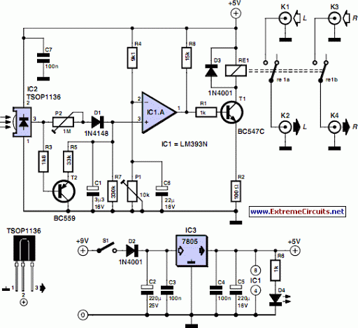
TV Muter Circuit
Many households are still equipped with tube-type television sets. If there is a desire to connect one of these large televisions to a stereo system to enhance the sound quality...
To connect a tube-type television to a stereo system, it is...
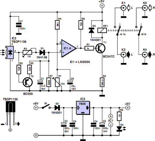
TV Muter Circuit
Many households still have tube-type television sets. Connecting one of these large televisions to a stereo system to enhance sound quality is generally straightforward, as numerous SCART to Cinch adapters are available in accessory stores. However, some television sets may...
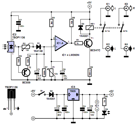
TV Muter Circuit
Many households still use tube-type television sets. Connecting these large televisions to a stereo system to enhance sound quality is usually straightforward, as numerous SCART to Cinch adapters are available in accessory shops. However, some television sets may present issues...
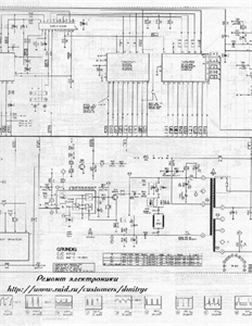
Circuit diagram of grundig 5441 tv
Circuit for Grundig 5441 TV. If there are any issues related to this circuit, please provide additional information about the problem for further assistance. By accessing the Fixya site, users acknowledge that they have read and agreed to its Terms....
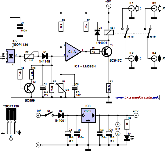
TV Muter Circuit
Many households still use tube-type television sets. Connecting one of these large televisions to a stereo system to enhance sound quality is generally straightforward, as numerous SCART to Cinch adapters are available in accessory shops. However, with some television sets,...
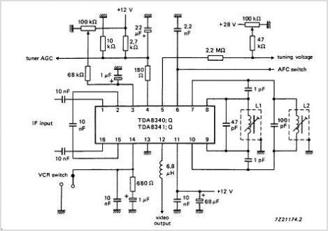
TDA8340 Television If Amplifier And Demodulator - Nxp Semiconductors
The TDA9813T is an integrated circuit designed for processing vision intermediate frequency (IF) signals and dual frequency modulation (FM) demodulation of sound. It operates with a single reference QSS-IF in television (TV) and video cassette recorder (VCR) applications, specifically supporting...
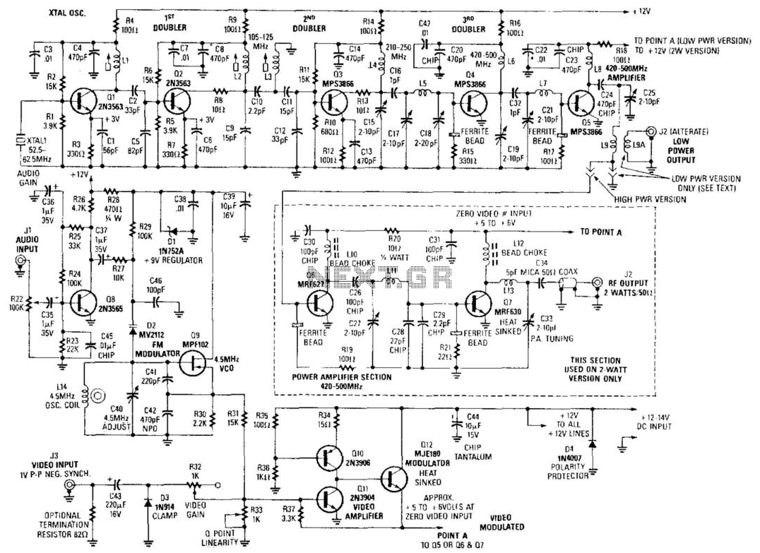
Amateur Television Transmitter
Although the unit was designed for 2 W operation, the Q6 and Q7 stages and their associated components can be omitted. Approximately 1 to 30 mW of RF can be obtained by link coupling to L9. A complete set of...

Working Principle Television (TV)
Before studying the working principles of a TV receiver, it is important to understand the journey of the image displayed on the television. The images seen on TV are produced by a camera. The object image captured by the camera...
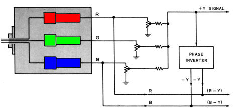
RCA CT-100 Color Television Design
If you have not already read the CT-100 restoration article, it is recommended to start there. It chronicles the discovery of a CT-100 and its restoration to working condition. This article discusses the internal components of the CT-100. After highlighting...