


22kW and below hoist with Y- transfer power-saving circuit
#hoist
#power-saving
#Y-transfer
#contactor
#CJ20-10A
#22kW
#motor
#control circuit
#energy efficiency
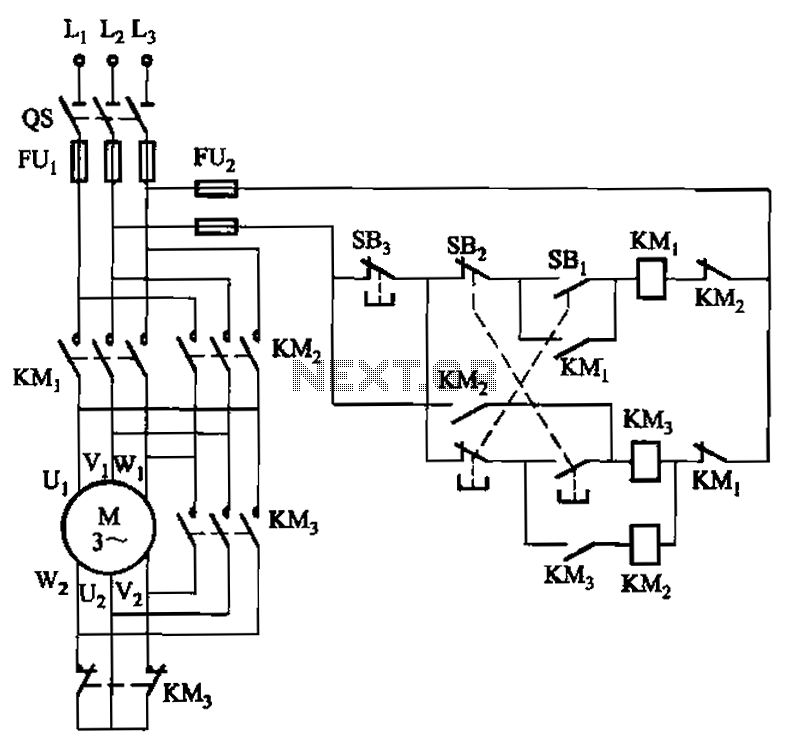
Description: A hoist rated at 22kW and below is equipped with a power-saving Y-conversion circuit, as depicted in the figure. This circuit enhances the standard hoist design by incorporating a CJ20-10A exchange contactor. The implementation of the Y-conversion circuit during the downward stroke of the hoist can achieve energy savings ranging from 40% to 60%.
The described hoist system utilizes a Y-conversion circuit to optimize energy consumption during operation. The Y-conversion method is particularly effective in reducing power usage when the hoist is in its downward stroke phase. The circuit modification involves integrating a CJ20-10A exchange contactor, which facilitates the transition between different operational modes. This contactor plays a critical role in managing the electrical load and ensuring that the hoist operates efficiently.
The standard hoist circuit typically operates at full power, which can lead to unnecessary energy consumption. By incorporating the Y-conversion circuit, the system can reduce the voltage and current supplied to the motor during specific phases of operation, particularly when lowering loads. This reduction in power not only conserves energy but also minimizes wear and tear on the motor, potentially extending its operational lifespan.
In practical applications, the energy savings achieved through this circuit can significantly lower operational costs, making it an attractive solution for facilities utilizing hoisting equipment. The use of advanced control mechanisms and contactors ensures that the system remains responsive and reliable while maximizing efficiency. Overall, the integration of the Y-conversion circuit represents a significant advancement in hoist technology, providing both environmental and economic benefits.22kW and below hoist with power-saving circuit Y- conversion circuit shown in Fig. The circuit on the basis of general hoist circuit adds a CJ20-10A exchange contact contactor KMa. Using Y- conversion circuit in the hoist downward stroke can be saving 40% -60%.
The described hoist system utilizes a Y-conversion circuit to optimize energy consumption during operation. The Y-conversion method is particularly effective in reducing power usage when the hoist is in its downward stroke phase. The circuit modification involves integrating a CJ20-10A exchange contactor, which facilitates the transition between different operational modes. This contactor plays a critical role in managing the electrical load and ensuring that the hoist operates efficiently.
The standard hoist circuit typically operates at full power, which can lead to unnecessary energy consumption. By incorporating the Y-conversion circuit, the system can reduce the voltage and current supplied to the motor during specific phases of operation, particularly when lowering loads. This reduction in power not only conserves energy but also minimizes wear and tear on the motor, potentially extending its operational lifespan.
In practical applications, the energy savings achieved through this circuit can significantly lower operational costs, making it an attractive solution for facilities utilizing hoisting equipment. The use of advanced control mechanisms and contactors ensures that the system remains responsive and reliable while maximizing efficiency. Overall, the integration of the Y-conversion circuit represents a significant advancement in hoist technology, providing both environmental and economic benefits.22kW and below hoist with power-saving circuit Y- conversion circuit shown in Fig. The circuit on the basis of general hoist circuit adds a CJ20-10A exchange contact contactor KMa. Using Y- conversion circuit in the hoist downward stroke can be saving 40% -60%.
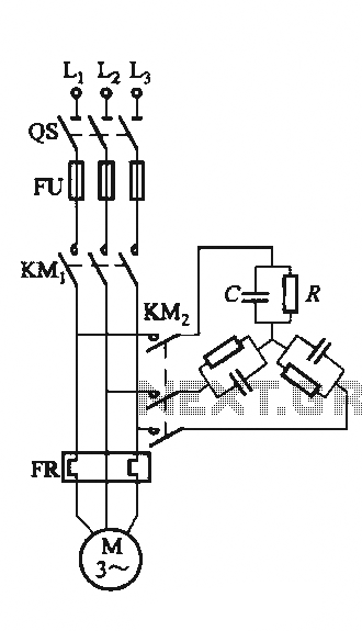
Single-speed motor excitation from the electrical braking circuit
The circuit illustrated in Figure 3-151 consists of capacitor banks arranged in a specific configuration. Figure 3-151 (a) depicts capacitor banks connected in a shaped configuration, which is suitable for shaped or Y-connected motors. Figure 3-151 (b) shows Y-connected capacitor...

Two-speed motor stator winding 2Y-2Y connection
As illustrated in Figure 3-105, this diagram depicts the lead wiring configuration for a two-speed motor stator with a 2Y/2Y connection.
The two-speed motor stator wiring diagram is essential for understanding the configuration and operation of the motor. In this setup,...
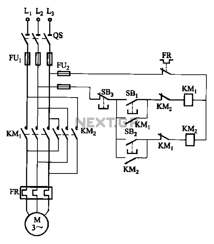
Start reversing contactor interlock control circuit
The circuit depicted in Figure 3-22 includes KMi and SBi as forward contacts and forward buttons, KMz and SB2 as reverse contactors and reverse buttons, with SB3 designated as the stop button.
The circuit in question is likely part of a...
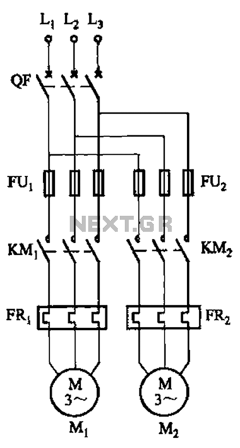
The use of a motor control switch automatic circuit a mutual investment
The circuit illustrated in Figure 3-64 operates with switch SA1 in the work position and switch SA2 in the standby position, allowing motor Mi to run while motor Mz remains on standby. In the event of downtime for motor Mi,...
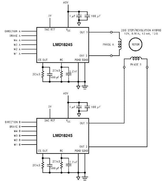
X and Y direction motor
This page is provided to the domain owner free by Sedo's Domain Parking. Disclaimer: The domain owner and Sedo maintain no relationship with third-party advertisers. References to any specific service or trademark are not controlled by Sedo or the domain...
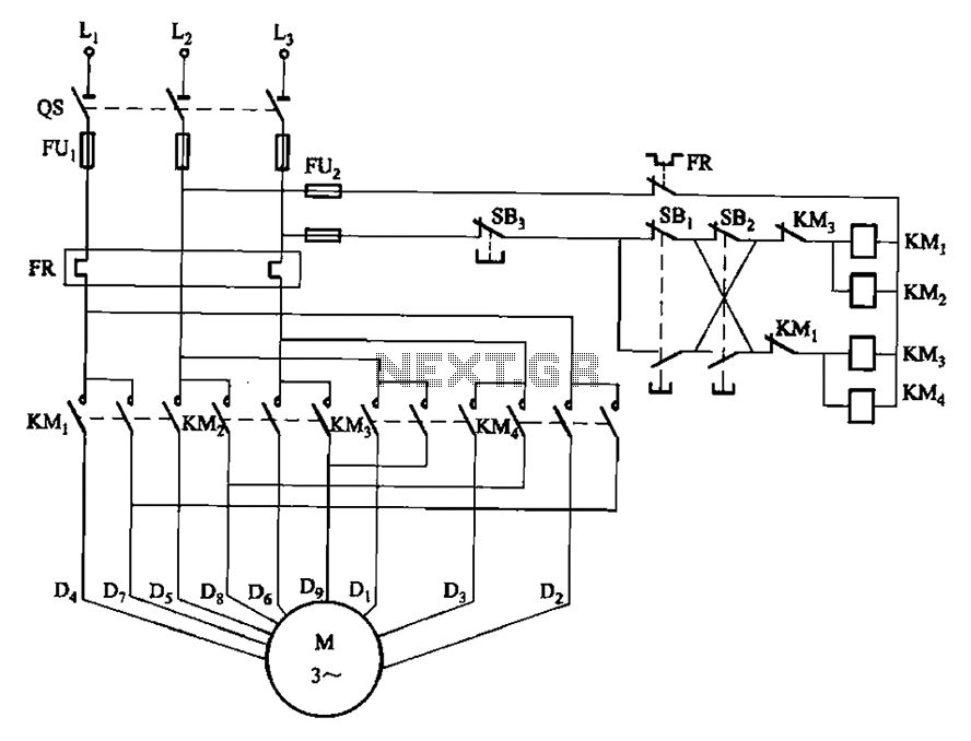
two-speed motor contactor control circuit two speeds in the same direction
The circuit depicted in Figure 3-112 features two operation buttons: SBi, which serves as the first speed operation button, and SBz, which operates the second speed class. Both buttons facilitate two speeds in the same direction.
The circuit design incorporates two...
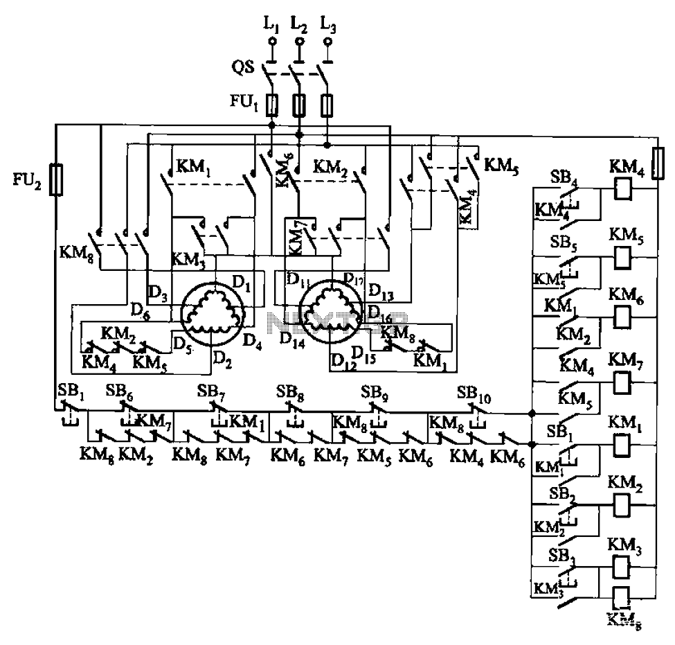
2Y-Y-2 - connection four-speed motor contactor control circuit
The circuit depicted in Figure 3-120 allows for the control of a motor with a capacity of less than the rated current of 5A by using an intermediate relay instead of a contactor. This circuit enables four forward running speeds...
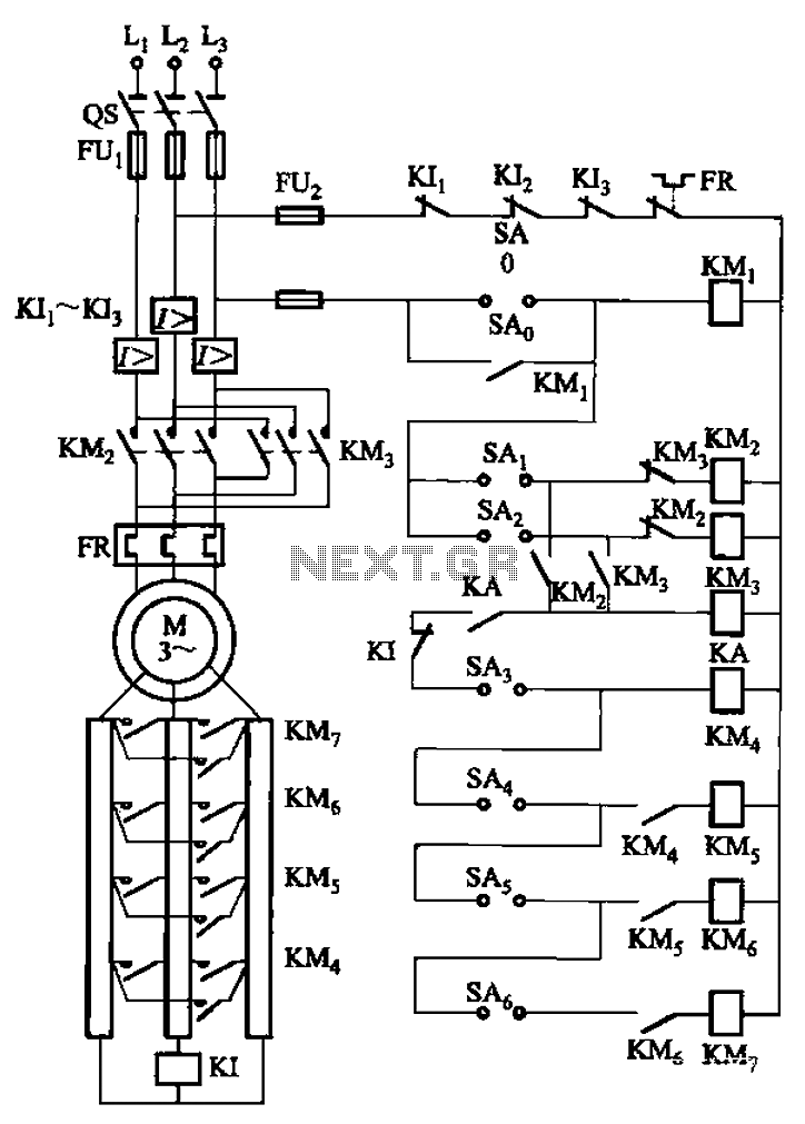
A control circuit reversing braking and reverse grading speed control function
The circuit depicted in Figure 3-168 utilizes a controller for speed grading and reversing control. A reverse brake is connected to the rotor circuit through an overcurrent relay, labeled KI, for control. The current relay KIi to KI3 serves as...
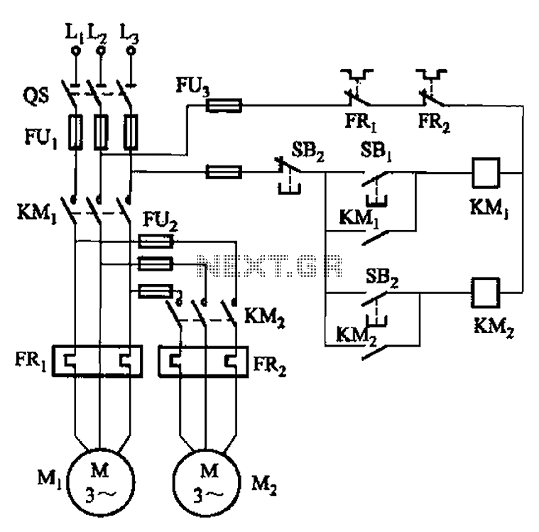
The main circuit in order to start the control circuit
The circuit illustrated in Figure 3-83 demonstrates that the contactor KMi is activated only after it is pulled, which indicates that the motor Mi has started for the first time. Following this, the contactor KM2 is then activated, indicating that...