


33kW and above windlass with Y- transfer power-saving circuit
#windlass
#Y-transfer
#power-saving
#33kW
#motor control
#high power
#energy efficiency
#conversion circuit
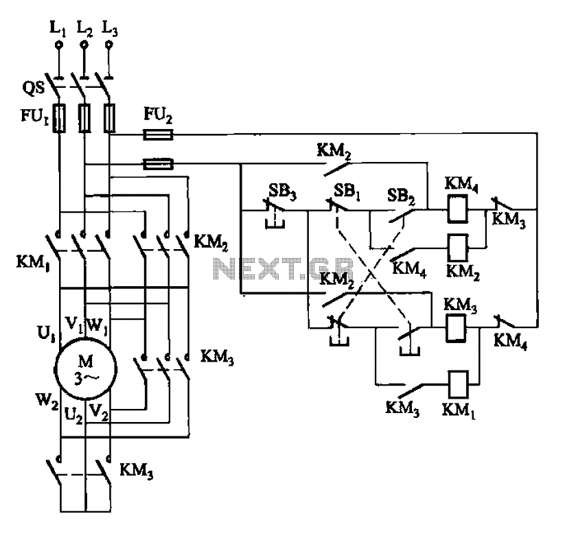
Description: 33 kW and above windlass with Y-conversion power-saving circuit
The circuit design for a windlass rated at 33 kW and above incorporates a Y-conversion power-saving mechanism. This design is crucial for optimizing the efficiency of the windlass, which is commonly used in marine applications for anchoring and mooring vessels.
The Y-conversion circuit enables the windlass motor to operate in a star (Y) configuration during startup, which reduces the initial inrush current and minimizes voltage drops in the system. Once the motor reaches a certain speed, the circuit can switch to a delta (Δ) configuration, allowing the motor to utilize its full power capacity for heavy lifting and hauling operations.
Key components of the circuit include contactors for switching between the Y and Δ configurations, a control relay to manage the transition based on motor speed, and protection devices such as circuit breakers to prevent overloads. The circuit may also incorporate a soft starter to further reduce mechanical stress and electrical surges during startup.
This power-saving circuit not only enhances the operational efficiency of the windlass but also contributes to energy conservation, making it an essential feature for modern marine equipment. Proper implementation of this circuit can lead to significant cost savings in energy consumption and improved performance in demanding marine environments.33kW and above windlass with Y- conversion power-saving circuit
The circuit design for a windlass rated at 33 kW and above incorporates a Y-conversion power-saving mechanism. This design is crucial for optimizing the efficiency of the windlass, which is commonly used in marine applications for anchoring and mooring vessels.
The Y-conversion circuit enables the windlass motor to operate in a star (Y) configuration during startup, which reduces the initial inrush current and minimizes voltage drops in the system. Once the motor reaches a certain speed, the circuit can switch to a delta (Δ) configuration, allowing the motor to utilize its full power capacity for heavy lifting and hauling operations.
Key components of the circuit include contactors for switching between the Y and Δ configurations, a control relay to manage the transition based on motor speed, and protection devices such as circuit breakers to prevent overloads. The circuit may also incorporate a soft starter to further reduce mechanical stress and electrical surges during startup.
This power-saving circuit not only enhances the operational efficiency of the windlass but also contributes to energy conservation, making it an essential feature for modern marine equipment. Proper implementation of this circuit can lead to significant cost savings in energy consumption and improved performance in demanding marine environments.33kW and above windlass with Y- conversion power-saving circuit
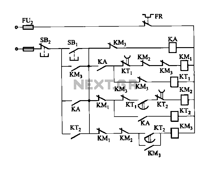
2 -Y- connection automatic three-speed motor acceleration control circuit
Figure 3-118 illustrates an automatic acceleration control circuit. This circuit employs a male contactor time relay, enabling the motor to start automatically at a low speed before transitioning to high-speed operation.
The automatic acceleration control circuit depicted in Figure 3-118 is...
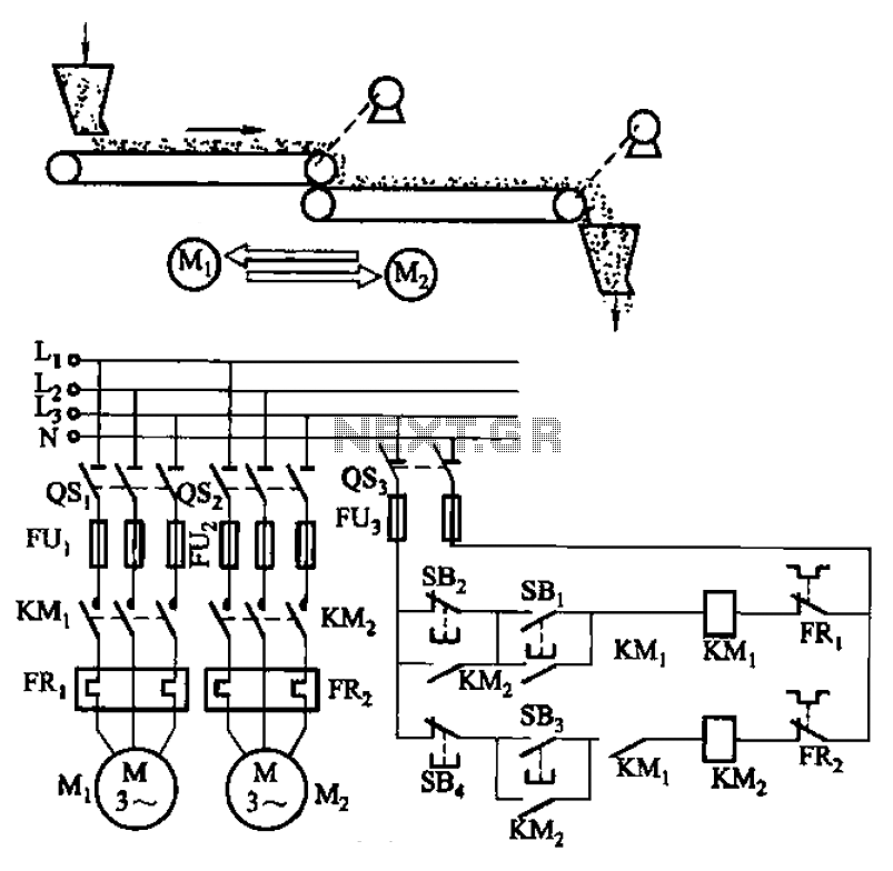
Belt conveyor interlock motor operation sequence control circuit
The circuit depicted in Figure 3-86 utilizes a line utilization time relay to control two motors, starting one before the other after an initial stall. The time relay KTi can be adjusted to modify the starting interval of the two...
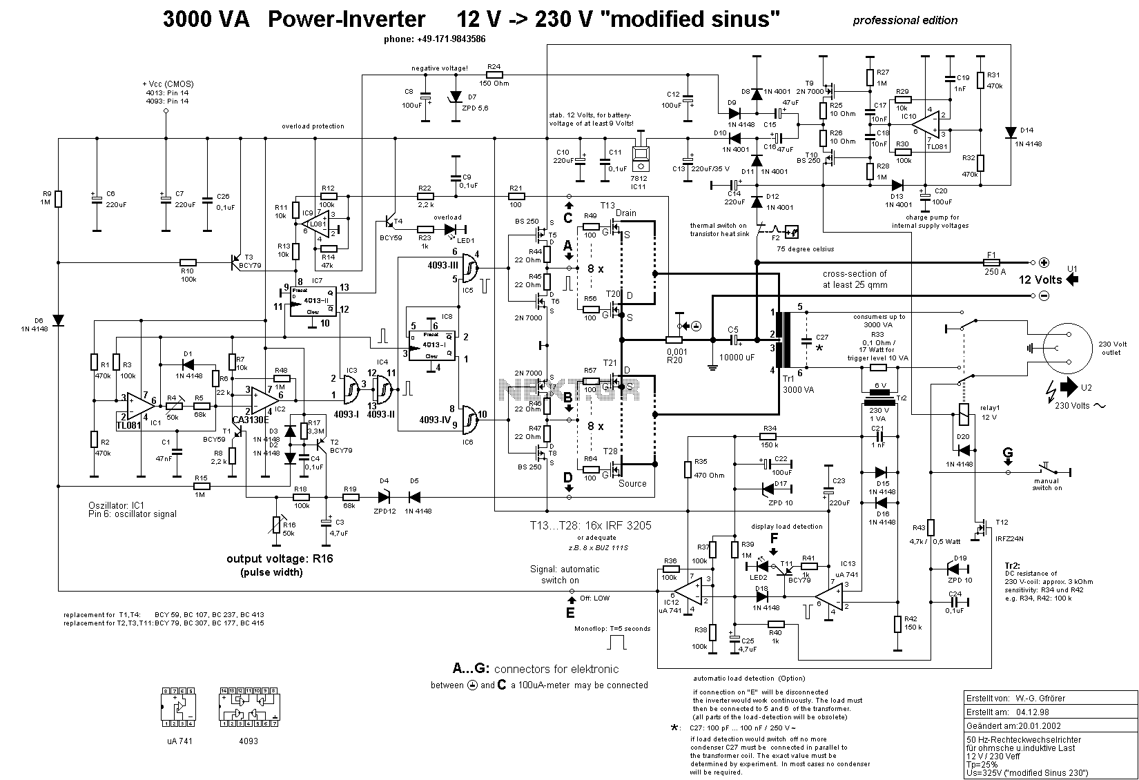
3000 Watt Inverter
This is a high-power inverter circuit designed to deliver an AC power output of 3000W. It converts 12 Volt DC battery voltage into a square wave voltage with a frequency of 50 Hz and a duty cycle of 25%.
The inverter...
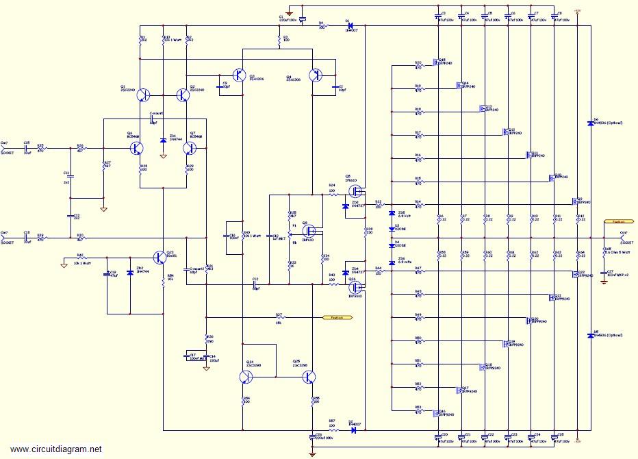
800W high power mosfet amplifier Schematic Diagram
This amplifier is suitable for various applications that demand high power, low noise, minimal distortion, and superior sound quality. Examples include subwoofer amplifiers, front-of-house (FOH) stage amplifiers, and individual channels of high-powered surround sound amplifiers. For a detailed explanation of...
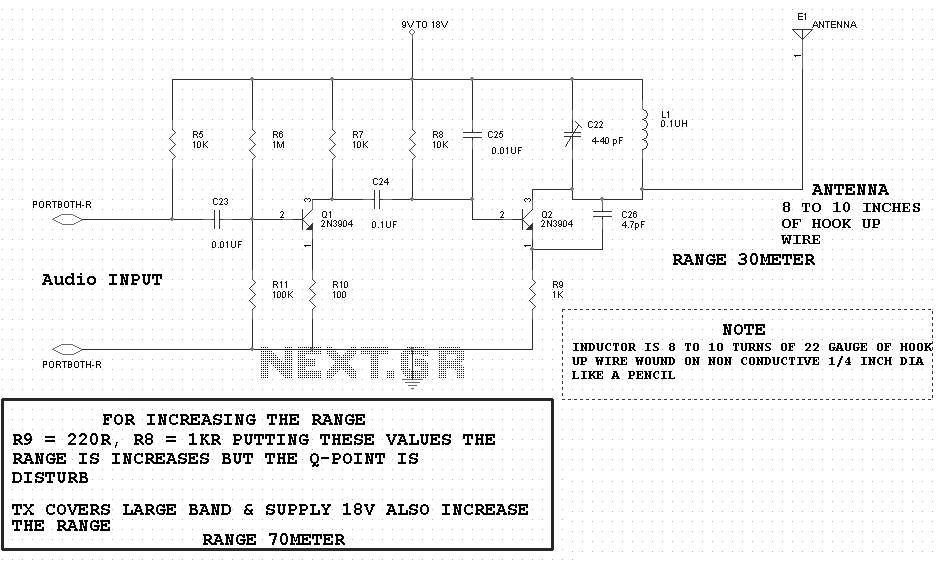
motor timer
The primary concept is to rotate the motor slightly every 15 seconds. A monofilament line conveys the motion to the ornament, which is wound by the motor and gradually unwinds as the ornament turns. The charging circuit includes a 1...
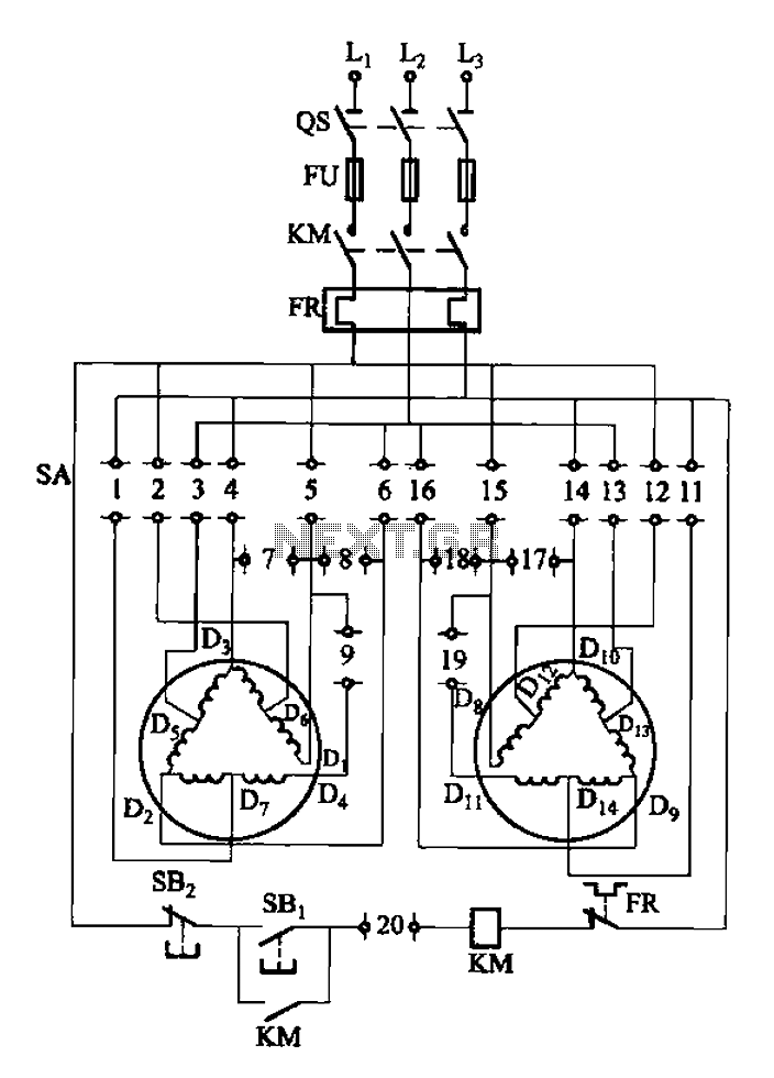
2Y-Y-2 - connection four-speed motor switch control circuit
The 3-119 circuit shown in the figure combines switch SA to realize the stator windings, specifically the 2, Y, and 2Y connections, which correspond to the motor speed n1.
The 3-119 circuit is designed to facilitate the control of motor speed...
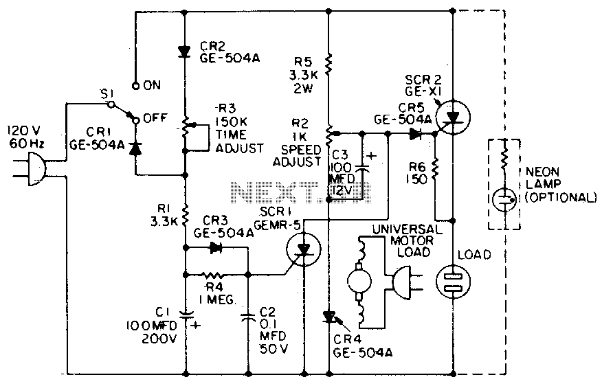
Universal motor control
When the time delay expires, SCR1 conducts and removes the gate signal from SCR2, which stops the motor. Both the time delay and motor speed are adjustable by potentiometers R2 and R3. If heavier motor loads are anticipated, use the...
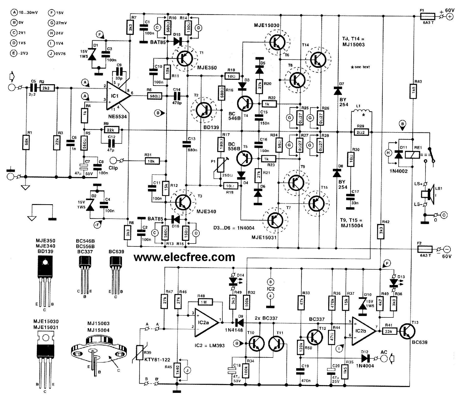
High power transistor amplifier circuits
This circuit is designed for friends who are interested in high-power amplifier circuits. It can deliver approximately 300 Watts RMS and operates as an OCL (Output Capacitor-Less) Class AB amplifier, providing high sound power while systematically protecting the loudspeaker from...
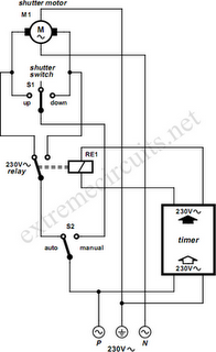
To Automate Rolling Shutter Motor
To automate the opening and closing of a rolling shutter using a time-controlled switch, additional wiring will be necessary.
To implement an automated system for a rolling shutter, a time-controlled switch can be utilized to manage the operation of the shutter....