


A star-delta switch automatically a start-up circuit
#star-delta
#switching
#motor starter
#three-phase
#industrial
#electrical safety
#KM contactor
#wiring diagram
#automation
#high power
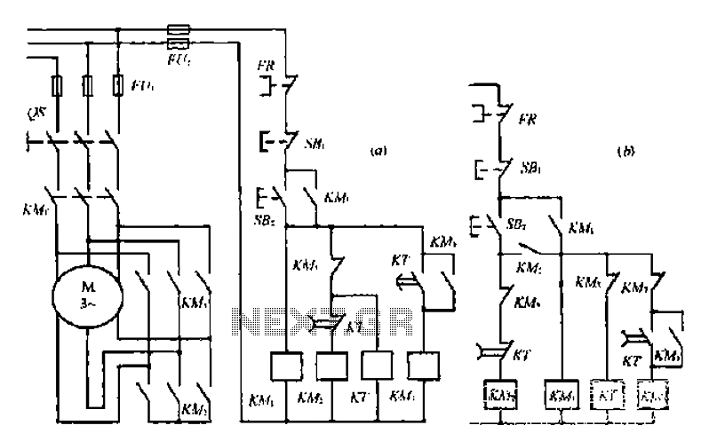
Description: A star-delta switch is utilized for starting circuits, commonly depicted in Figure I-5 (a) of the knife wiring. While this method is effective, it poses security risks. When the motor starts, it can create significant voltage fluctuations that may affect other devices on the same electrical line. The increased starting current can lead to frequent fuse blowouts and may reduce the lifespan of the equipment. The wiring diagram in Figure I-5 (a) illustrates the sequential control of KM1 and KM2, ensuring a safe and reliable operation. If KM2 experiences a fault, it will prevent the entire circuit from functioning, thereby protecting the motor from excessive current during startup. Additionally, this method minimizes the impact on other electrical appliances connected to the same line.
The star-delta starting method is a widely adopted technique for reducing the inrush current during the startup of three-phase induction motors. In this configuration, the motor is initially connected in a star (Y) configuration, which limits the voltage applied to each winding to 1/√3 of the line voltage. After a predetermined time, the motor is switched to a delta (Δ) configuration, allowing it to operate at full voltage and power.
The schematic for a star-delta starter typically includes contactors KM1 and KM2, which control the switching between the star and delta configurations. The control circuit may also include overload relays and timers to ensure proper operation and protection. The overload relay monitors the motor current and disconnects the circuit if it exceeds a predetermined threshold, preventing damage to the motor.
The sequential operation of the contactors is critical. When the start button is pressed, KM1 is energized, connecting the motor windings in the star configuration. After a specified time delay, which can be adjusted based on the motor characteristics and application requirements, KM1 is de-energized, and KM2 is energized, switching the motor to the delta configuration. This transition must be carefully timed to avoid any overlap that could cause short circuits or damage to the contactors.
In addition to the core components, auxiliary contacts may be included in the design to provide feedback to the control circuit, indicating whether the motor is in the star or delta configuration. This feedback can be used to implement additional safety features, such as interlocks that prevent the motor from being started in the delta configuration if it is not running smoothly.
Overall, the star-delta starter circuit is an essential design for applications requiring reduced starting current, improved motor protection, and enhanced operational reliability. Proper design and implementation of this circuit contribute to the longevity and efficiency of three-phase induction motors in industrial settings.A star-delta Bolt switching a starting circuit. Often used in Figure I-5 (a) of the knife; wiring. Therapy, but there are security risks in this method, that is, when KM; Jie b ranch sleepy species pecking read J1: when the road, the motor will become barrier shoulder press movement. Thus ln1 just on the grid (spoon impact .i; I play now instantaneous voltage tll large fluctuations affect other same line of electrical work two full-Hill J heir, the starting current increases fuse blows frequently.
increased shoulder movement times the number. What the machine so that l release NPC life is reduced. the method is herein referred carp wing of an army. indiscriminately I 5 (a) of pickled wiring diagram l to a 5 l D) wiring playing method. ir] - on KM2 and KMi were sequential control, so that the boat} felt a safe and reliable way. If K M2 [some kind of D; c shut small suction flute, the entire circuit is not working to protect the motor from the start of the Qiang full of pus. Protection also Suo Ran circles often stop by a small impact, it does not affect the use of electrical appliances on the same line as T- lIi often.
The star-delta starting method is a widely adopted technique for reducing the inrush current during the startup of three-phase induction motors. In this configuration, the motor is initially connected in a star (Y) configuration, which limits the voltage applied to each winding to 1/√3 of the line voltage. After a predetermined time, the motor is switched to a delta (Δ) configuration, allowing it to operate at full voltage and power.
The schematic for a star-delta starter typically includes contactors KM1 and KM2, which control the switching between the star and delta configurations. The control circuit may also include overload relays and timers to ensure proper operation and protection. The overload relay monitors the motor current and disconnects the circuit if it exceeds a predetermined threshold, preventing damage to the motor.
The sequential operation of the contactors is critical. When the start button is pressed, KM1 is energized, connecting the motor windings in the star configuration. After a specified time delay, which can be adjusted based on the motor characteristics and application requirements, KM1 is de-energized, and KM2 is energized, switching the motor to the delta configuration. This transition must be carefully timed to avoid any overlap that could cause short circuits or damage to the contactors.
In addition to the core components, auxiliary contacts may be included in the design to provide feedback to the control circuit, indicating whether the motor is in the star or delta configuration. This feedback can be used to implement additional safety features, such as interlocks that prevent the motor from being started in the delta configuration if it is not running smoothly.
Overall, the star-delta starter circuit is an essential design for applications requiring reduced starting current, improved motor protection, and enhanced operational reliability. Proper design and implementation of this circuit contribute to the longevity and efficiency of three-phase induction motors in industrial settings.A star-delta Bolt switching a starting circuit. Often used in Figure I-5 (a) of the knife; wiring. Therapy, but there are security risks in this method, that is, when KM; Jie b ranch sleepy species pecking read J1: when the road, the motor will become barrier shoulder press movement. Thus ln1 just on the grid (spoon impact .i; I play now instantaneous voltage tll large fluctuations affect other same line of electrical work two full-Hill J heir, the starting current increases fuse blows frequently.
increased shoulder movement times the number. What the machine so that l release NPC life is reduced. the method is herein referred carp wing of an army. indiscriminately I 5 (a) of pickled wiring diagram l to a 5 l D) wiring playing method. ir] - on KM2 and KMi were sequential control, so that the boat} felt a safe and reliable way. If K M2 [some kind of D; c shut small suction flute, the entire circuit is not working to protect the motor from the start of the Qiang full of pus. Protection also Suo Ran circles often stop by a small impact, it does not affect the use of electrical appliances on the same line as T- lIi often.
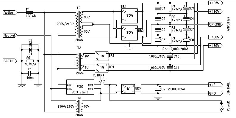
power supply for 1500 watt audio power amplifier
Power supply for a 1500-watt audio power amplifier. This power supply circuit is paired with a high-power audio amplifier rated at 1500 watts. A serious approach is required to design the power supply for the amplifier. First, a step-down transformer...
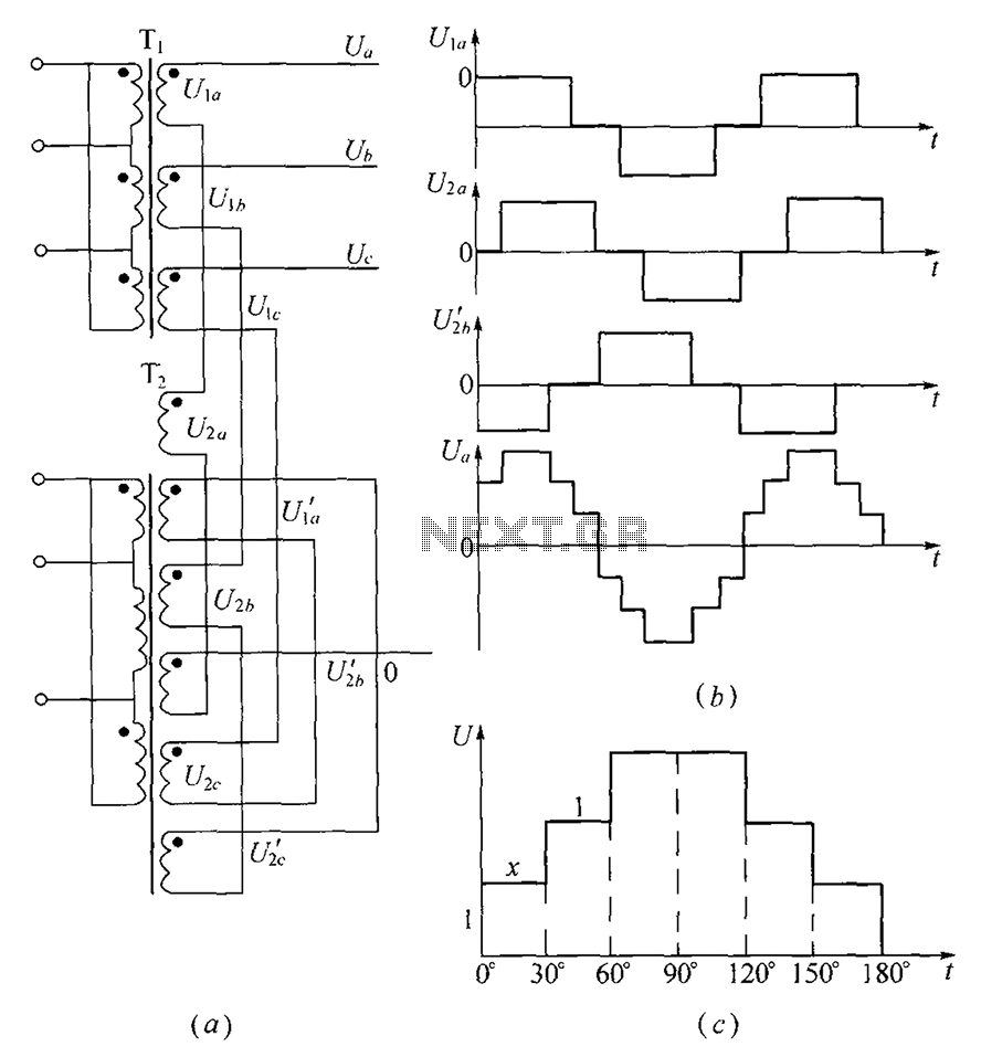
Three-phase step wave inverter output transformer winding connection and the output voltage waveform
As shown, (a) for the three-phase step wave inverter output transformer winding connections; (b) in the figure, its output waveform.
The three-phase step wave inverter is designed to convert direct current (DC) into a three-phase alternating current (AC) output. This inverter...
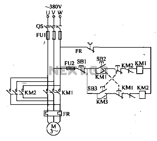
Double interlocking three-phase asynchronous motor control circuit
The forward and reverse dual interlock control circuit is based on the control circuit depicted in Figure 4-4, with an enhancement that incorporates a composite mechanical button interlock. The advantage of this circuit is that it allows the motor to...

1976 dodge aspen wiring diagram
The Dodge Aspen was a compact car produced from 1976 to 1980 by Chrysler Corporation's Dodge division. The 1976 Aspen model year was available as a 2-door coupe, 4-door sedan, or 4-door station wagon, and it came in three trim...
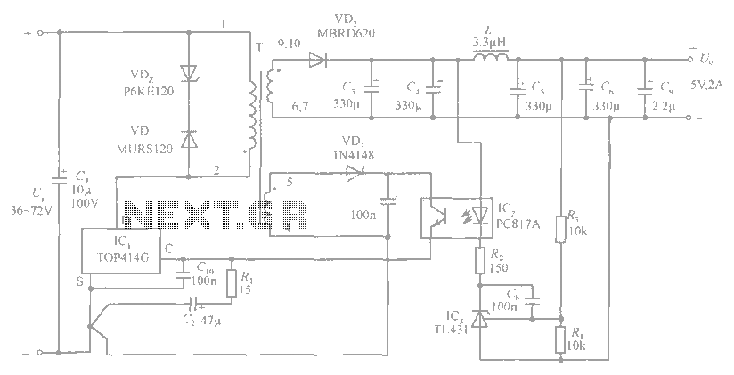
5V / 2A isolated switching power supply circuit diagram
The circuit diagram includes an input filter capacitor C1 and a primary clamp composed of VDz and VD1. The resistor R1 is connected to the control terminal. C2 serves as a bypass capacitor. The TOP414GC-S is connected in parallel to...
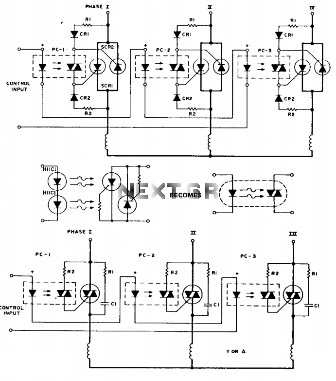
Three-phase switch
To simplify the following schematics and facilitate easy understanding of the principles involved, the following schematic substitution is used. Note that the triac driver is of limited use at 3-phase voltage levels. The following are three-phase switches for low voltage....
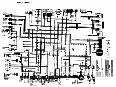
Honda Motorcycle CB750F Wiring Diagram
The following image illustrates the electrical wiring connection diagram for the Honda Motorcycle CB750F. It details the connections between various Honda components, including the right turn signal indicator light, oil pressure warning light, neutral indicator, high beam indicator, turn signal...
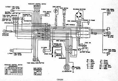
CB125S WIRING DIAGRAM
CB125S Wiring Diagram Manual PDF Download.
The CB125S Wiring Diagram Manual provides a comprehensive guide for understanding the electrical system of the CB125S motorcycle. This manual includes detailed wiring diagrams that illustrate the connections between various electrical components, such as the...
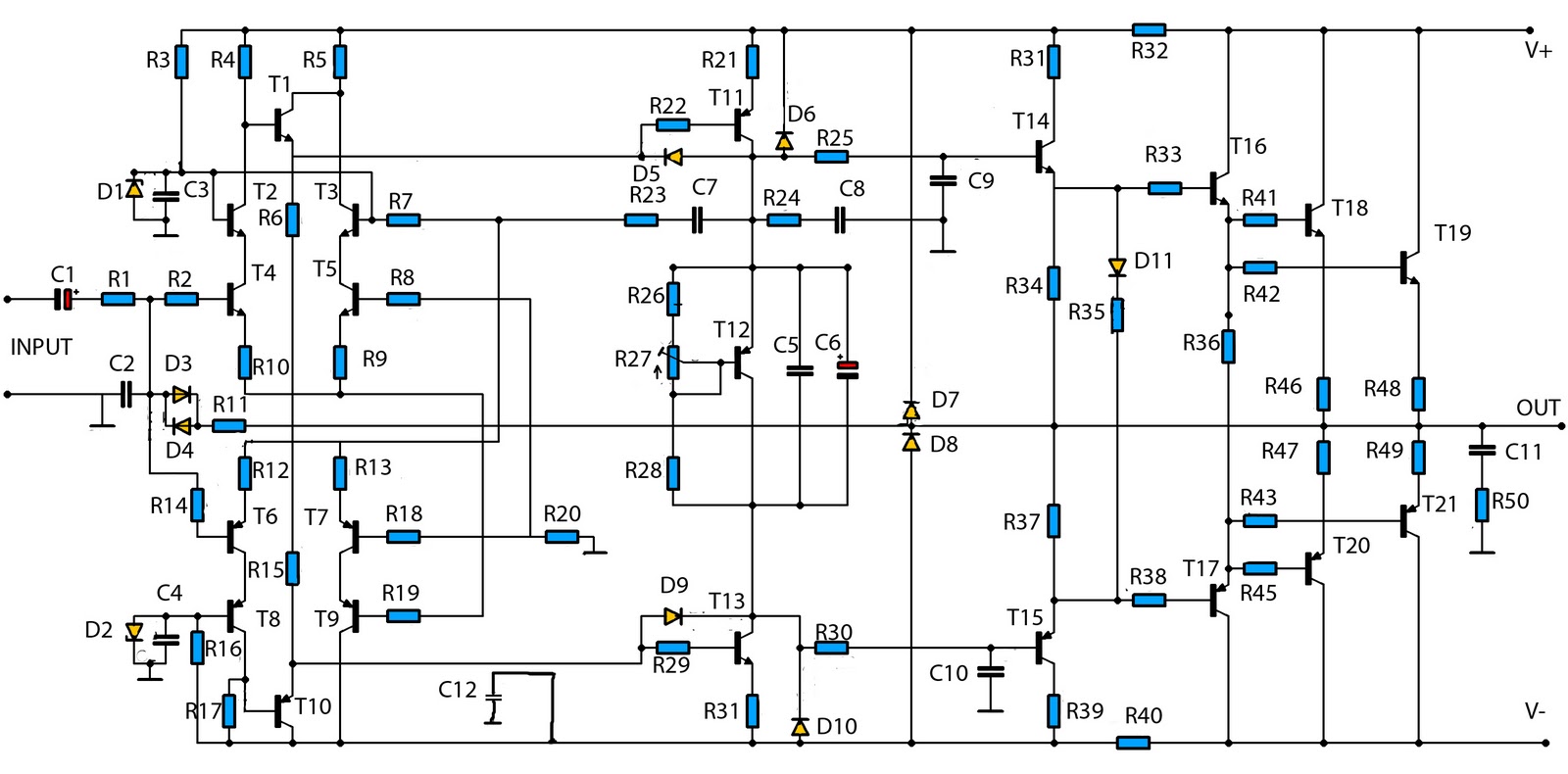
2800w high power audio amplifier
The mono high power amplifier is rated at 1400 W. To create a stereo high power amplifier, which would require a total of 2800 W, the necessary components and PCB must be doubled. The schematic circuit diagram provided is incomplete....