


Arduino controlling a DC Motor
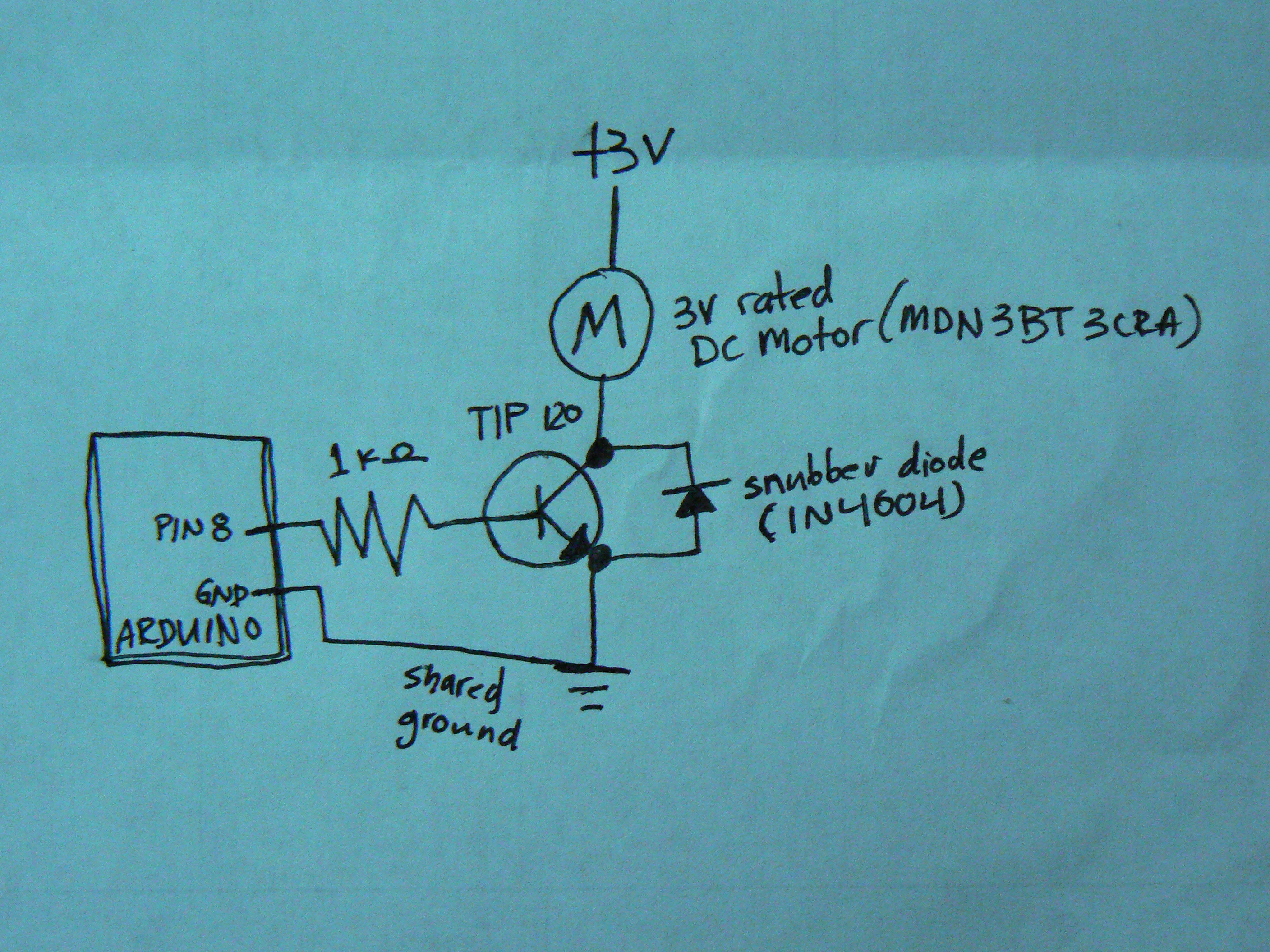
Description: When controlling motors with a microcontroller, the snubber is quite important. This configuration is not commonly seen, as the snubber is typically placed across the motor itself. The general concept is that charge builds up on the motor coil, and when the transistor is turned off, the diode allows current to flow and dissipate the charge. It is suggested to move the diode across the motor for improved results.
In motor control circuits, especially those utilizing microcontrollers, the implementation of snubber circuits is critical for protecting components from voltage spikes and ensuring stable operation. Snubber circuits typically consist of a resistor and capacitor in series, connected across the motor terminals. This configuration helps absorb the inductive kickback generated when the motor is switched off, preventing damage to the microcontroller and other components in the circuit.
When a transistor controlling the motor is turned off, the energy stored in the motor's inductance can generate a high voltage spike. This spike can lead to excessive voltage levels that may damage the transistor or the microcontroller. By placing a diode across the motor, the reverse current can flow through the diode, allowing the energy to dissipate safely. This method effectively clamps the voltage, protecting sensitive components.
For optimal performance, it is advisable to consider the placement of the diode. Moving the diode directly across the motor terminals can enhance the circuit's response to inductive spikes, allowing for quicker dissipation of energy. This adjustment can lead to improved reliability and longevity of the motor control system.
In summary, integrating a snubber circuit and appropriately positioning the diode are essential practices in motor control applications involving microcontrollers. These strategies help mitigate the effects of inductive kickback, ensuring the safe and efficient operation of the motor control system.When controlling motors with a microcontroller (like shown), the snubber is really pretty important. I haven`t seen this configuration, though, and typically the snubber is placed across the motor itself. The general idea is that there is charge that builds up on the motor coil, and, when the transistor is "off", the diode allows a current to flow and the
charge to dissipate. Try moving that diode across the motor for better results. [url= [url= controlling a DC Motor: circuit diagram[/url] by [url= on Flickr [url= [url= controlling a DC Motor: circuit diagram[/url] by [url= on Flickr [url= [url= controlling a DC Motor: circuit diagram[/url] by [url= on Flickr [url= [url= controlling a DC Motor: circuit diagram[/url] by [url= on Flickr [url= [url= controlling a DC Motor: circuit diagram[/url] by [url= on Flickr [url= [url= controlling a DC Motor: circuit diagram[/url] by [url= on Flickr [url= [url= controlling a DC Motor: circuit diagram[/url] by [url= on Flickr [url= controlling a DC Motor: circuit diagram[/url] by [url= on Flickr
Related Circuits
In motor control circuits, especially those utilizing microcontrollers, the implementation of snubber circuits is critical for protecting components from voltage spikes and ensuring stable operation. Snubber circuits typically consist of a resistor and capacitor in series, connected across the motor terminals. This configuration helps absorb the inductive kickback generated when the motor is switched off, preventing damage to the microcontroller and other components in the circuit.
When a transistor controlling the motor is turned off, the energy stored in the motor's inductance can generate a high voltage spike. This spike can lead to excessive voltage levels that may damage the transistor or the microcontroller. By placing a diode across the motor, the reverse current can flow through the diode, allowing the energy to dissipate safely. This method effectively clamps the voltage, protecting sensitive components.
For optimal performance, it is advisable to consider the placement of the diode. Moving the diode directly across the motor terminals can enhance the circuit's response to inductive spikes, allowing for quicker dissipation of energy. This adjustment can lead to improved reliability and longevity of the motor control system.
In summary, integrating a snubber circuit and appropriately positioning the diode are essential practices in motor control applications involving microcontrollers. These strategies help mitigate the effects of inductive kickback, ensuring the safe and efficient operation of the motor control system.When controlling motors with a microcontroller (like shown), the snubber is really pretty important. I haven`t seen this configuration, though, and typically the snubber is placed across the motor itself. The general idea is that there is charge that builds up on the motor coil, and, when the transistor is "off", the diode allows a current to flow and the
charge to dissipate. Try moving that diode across the motor for better results.
Electronic-bird-chirper
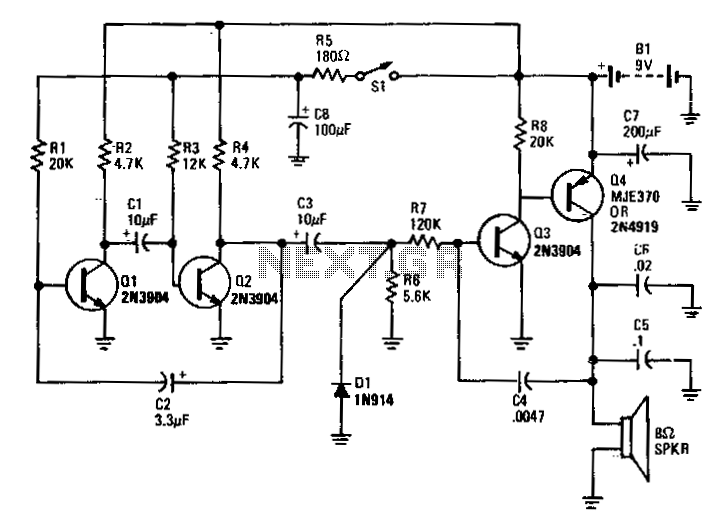
Transistors Q1 and Q2 form the two halves of a free-running multivibrator, with the frequency determined by the voltage across capacitor C8. This capacitor is charged and discharged by the operation of switch S1. Transistors Q3 and Q4 constitute a...
instrumentation amplifier How to Read Wheatstone Bridge negative voltage with Arduino
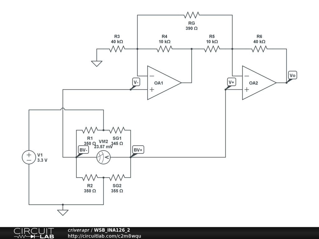
A half-bridge setup is utilized with strain gauges and an INA126 to amplify the voltage. The voltage can be read accurately when the lever is bent in one direction; however, no reading is obtained when the lever is bent in...

Tl5001 Pulse-width-modulation (pwm) Controller Coupled With A Tps2817 Mosfet Driver
The TLE6282G is an H-Bridge and Half Bridge Driver IC designed for high-current DC brush motor applications in PWM control mode. It is suitable for use in injector and valve applications across 12V, 24V, and 42V power networks. This IC...
improved 3 transistor audio amp
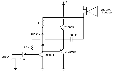
This circuit is similar to the previous one but employs positive feedback to enhance the amplitude delivered to the speaker. It is adapted from a small 5-transistor radio that utilizes a 25-ohm speaker. In the earlier circuit, the load resistor...
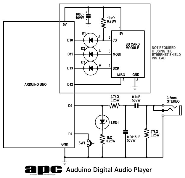
Arduino Digital audio player
In this series, a diverse exploration of how Arduino interacts with various real-world devices has been presented, from servo motors to ultrasonic range finders, TVs to humidity sensors. The focus now shifts to generating sound using Arduino. The project involves...
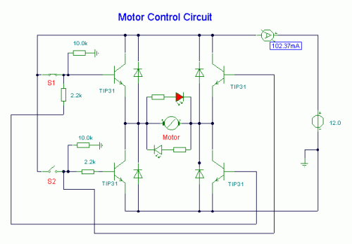
DC Motor Control Circuit
S1 and S2 are normally open, push-to-close, momentary switches. The diodes, which can be either red or green, serve solely to indicate the direction of operation. The TIP31 transistors may need to be adjusted based on the specifications of the...
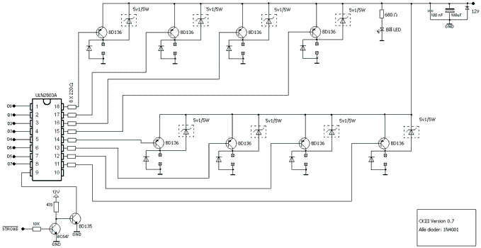
8 Channel software controlled fanbus with PWM
This article was previously published, but the intention is to spread the idea further, potentially inspiring new concepts. An improved version was being developed using an ULN2803A instead of multiple BC547B transistors and optional Zener diodes to ensure that the...
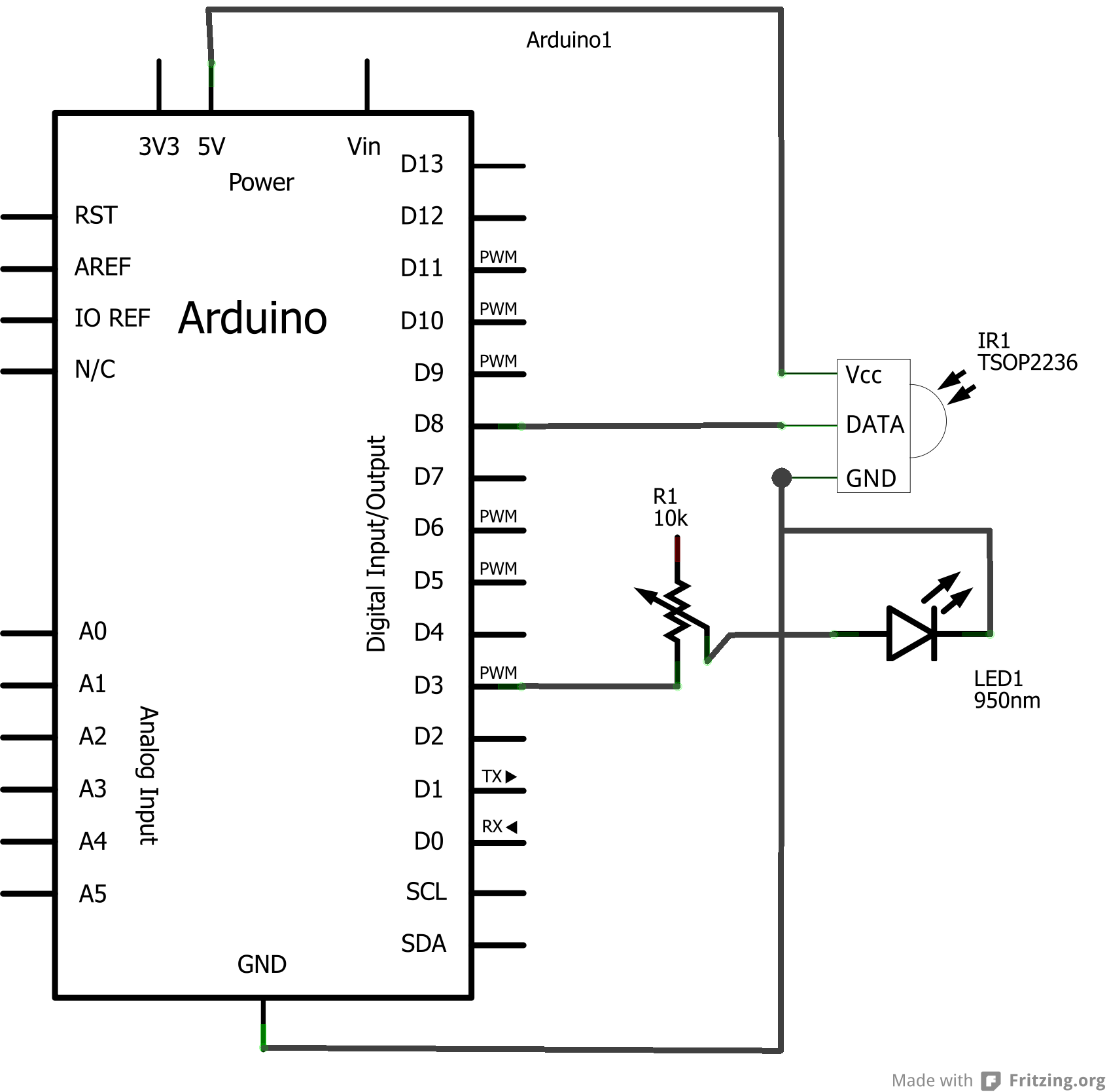
Arduino based electricity meter
The concept involves using infrared light that is reflected by a disc, except for a dark red line. The sensor receives the reflected light, allowing the Arduino to track the number of revolutions. The infrared sensor is tuned to a...
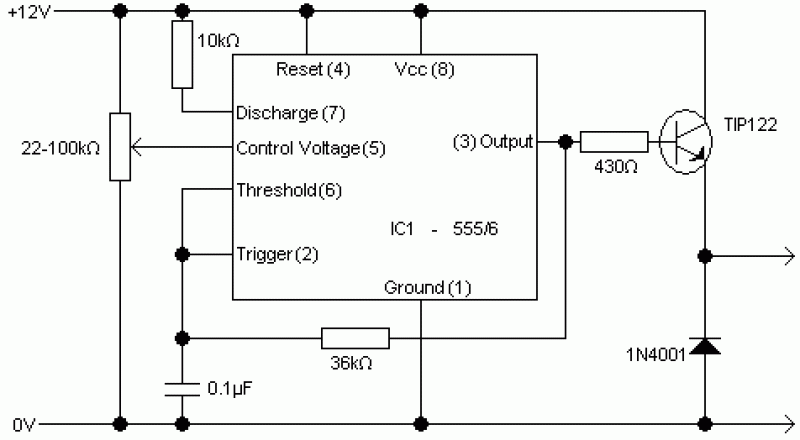
PWM Motor Control circuit
This controller is designed primarily for controlling model trains and can deliver approximately 12-15 Volts, though it operates effectively at voltages as low as 3V, including a 6V supply for certain accessories. The maximum output current is theoretically around 5...