


Bi-directional Control Of Motors And The H-Bridge
#H-Bridge
#DC motor
#bidirectional
#motor driver
#switching
#direction control
#power connections
#reverse rotation
#circuit configuration
#electronics
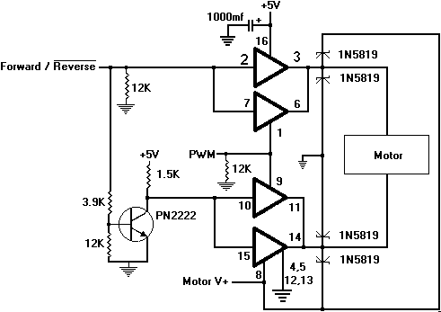
Description: Reversing the DC power connections on a motor causes its shaft to rotate in the opposite direction. One method to control the direction is by using switches arranged in a specific configuration known as an H-Bridge. For instance, when the motor's positive terminal is connected to Motor V+ and its negative terminal is connected to ground, the motor runs forward. Conversely, it will run in reverse when the connections are reversed.
To run the motor forward, switches A and D should be activated, while switches B and C should be turned on to run the motor in reverse. A table illustrates the possible switch combinations, where a '1' indicates an active switch and a '0' indicates an inactive switch. It is important to note that seven combinations must be avoided to prevent shorting the power supply. The usable combinations include forward and reverse, one off state, and optionally one braking state.
The braking mechanism requires some explanation. As a motor's armature rotates, it passes through the magnetic fields, inducing an electrical current in the winding. When the motor shaft is spun, a voltage can be measured at its terminals, effectively turning it into a generator. Shorting the motor's terminals creates resistance against the spinning shaft due to the opposing magnetic field generated by the induced current, resulting in a braking effect. Both braking combinations involve shorting the motor terminals together.
Various devices can serve as switches, including mechanical switches, transistors, and relays. The TIP120 transistor is suitable for low currents, but requires a heat sink for high currents due to a voltage drop of approximately 0.7 volts between the collector and emitter. For example, at 5 amps, the TIP120 would dissipate 3.5 watts of power, which could otherwise be utilized by the load if a more efficient device were used.
In this application, a Metal Oxide Semiconductor Field Effect Transistor (MOSFET) is preferred. MOSFETs are available in two types: N-channel and P-channel, with the N-channel variant being employed here. An enhancement mode N-channel MOSFET is activated by applying a positive voltage to the gate relative to the source, enhancing conductivity between the source and drain. The conductivity unit is measured in mhos, which is ohm spelled backward. The IRF3708 MOSFET will turn on when the gate voltage is approximately 2 volts higher than the source. The gate is insulated from the rest of the device, and its operation relies on the field effect across a very thin insulator, which can be damaged by static electricity.
Caution is advised when handling MOSFETs, as leads may be shorted with conductive materials during shipping. This shorting material should remain in place until the device is ready for installation. Additionally, it is essential to ensure proper grounding before handling a MOSFET.
For power calculations, the resistance from the source to drain of the IRF3708 is significantly high when off, but only 0.029 ohms when on. This low resistance allows for efficient operation, reducing power loss compared to traditional transistors. The relationship between voltage, current, and resistance (V = I * R) can be applied to determine the power dissipation in the circuit.Reverse the DC power connections on such a motor and its shaft will rotate in the opposite direction. One way to control direction is to use switches arranged in the following manner: This configuration is called an H-Bridge due to its shape.
Let`s say that the motor runs forward when its + terminal is connected to Motor V+ and its - terminal is connected to ground. It will run in reverse when the opposite is true. Turn on switch A and switch D and the motor will run forward. Turn on switch B and switch C and it will run in reverse. The following table shows all of the possibilities. A 1 means a switch is on, and a 0 means it`s off: Only a few of the possibilities are needed. In fact, seven of the combinations must be avoided because they short out the power supply. We can use the forward and reverse, one of the offs and, optionally, one of the brakes. The braking action might need a little explaining. A motor`s armature will pass through the fields of the magnets when it is turning, as will the wire that`s wound around the armature. That will induce an electrical current in the wire. Spin the shaft of a motor and you can measure a voltage at its terminals; it has become a generator. Short the motor`s terminals and you will feel it resist your attempts to spin the shaft. That`s because the magnet that`s formed by the current induced in the armature winding is opposite to that of the motor`s field magnet.
The opposite poles attract, resulting in a braking action. Both of the brake combinations short the terminals of the motor together. There are a variety of devices that can be used for switches, including common mechanical switches, transistors and relays. The TIP120 will work for low currents, but a heat sink is needed for high current. The reason is that most transistors have a voltage drop between their collector and emitter of about.
7 volts. Recall that power is P = I * V. With say, 5 amps and a. 7V drop, the TIP120 will dissipate 5 *. 7 = 3. 5 watts. That`s wasted power that could have been used by the load with a more efficient device. The switch to be used here is a Metal Oxide Semiconductor Field Effect Transistor, or MOSFET. MOSFETs come in two polarities called N and P channel. The one to be used here is an N channel device. A schematic representation and a picture showing the pin designations is below (the sunflower is almost never included). Notice that the Drain is also connected to the metal tab, making it necessary to insulate the MOSFET when using a heatsink: An enhancement mode N channel MOSFET is turned on by making the gate more positive than the source.
What is enhanced is the conductivity between source and drain. The unit of conductivity is the mho, which is simply ohm spelled backwards. The IRF3708 used here will turn on if the gate is about 2 volts more positive than the source (see IRF3708. PDF ). The gate is not physically connected to the rest of the device. It influences the device by the fact that it is on one side of a very thin insulator, and works by means of the imposed field effect.
In fact, the insulator is so thin that it can be ruptured by static voltages as weak as that from a piece of plastic. Great care should be taken when working with a MOSFET. The leads are sometimes shorted with a piece of wire or conductive foam when shipped. The shorting material should not be removed until the last moment when installing the device. Also, make sure you are grounded or have at least touched ground before touching a MOSFET. Now let`s calculate power again. The resistance from Source to Drain of the IRF3708 is very high when it is off, but a maximum of only.
029 ohms when it is on. Recall from How To Read A Schematic that V = I * R. That means we can replace the V in the power equation
To run the motor forward, switches A and D should be activated, while switches B and C should be turned on to run the motor in reverse. A table illustrates the possible switch combinations, where a '1' indicates an active switch and a '0' indicates an inactive switch. It is important to note that seven combinations must be avoided to prevent shorting the power supply. The usable combinations include forward and reverse, one off state, and optionally one braking state.
The braking mechanism requires some explanation. As a motor's armature rotates, it passes through the magnetic fields, inducing an electrical current in the winding. When the motor shaft is spun, a voltage can be measured at its terminals, effectively turning it into a generator. Shorting the motor's terminals creates resistance against the spinning shaft due to the opposing magnetic field generated by the induced current, resulting in a braking effect. Both braking combinations involve shorting the motor terminals together.
Various devices can serve as switches, including mechanical switches, transistors, and relays. The TIP120 transistor is suitable for low currents, but requires a heat sink for high currents due to a voltage drop of approximately 0.7 volts between the collector and emitter. For example, at 5 amps, the TIP120 would dissipate 3.5 watts of power, which could otherwise be utilized by the load if a more efficient device were used.
In this application, a Metal Oxide Semiconductor Field Effect Transistor (MOSFET) is preferred. MOSFETs are available in two types: N-channel and P-channel, with the N-channel variant being employed here. An enhancement mode N-channel MOSFET is activated by applying a positive voltage to the gate relative to the source, enhancing conductivity between the source and drain. The conductivity unit is measured in mhos, which is ohm spelled backward. The IRF3708 MOSFET will turn on when the gate voltage is approximately 2 volts higher than the source. The gate is insulated from the rest of the device, and its operation relies on the field effect across a very thin insulator, which can be damaged by static electricity.
Caution is advised when handling MOSFETs, as leads may be shorted with conductive materials during shipping. This shorting material should remain in place until the device is ready for installation. Additionally, it is essential to ensure proper grounding before handling a MOSFET.
For power calculations, the resistance from the source to drain of the IRF3708 is significantly high when off, but only 0.029 ohms when on. This low resistance allows for efficient operation, reducing power loss compared to traditional transistors. The relationship between voltage, current, and resistance (V = I * R) can be applied to determine the power dissipation in the circuit.Reverse the DC power connections on such a motor and its shaft will rotate in the opposite direction. One way to control direction is to use switches arranged in the following manner: This configuration is called an H-Bridge due to its shape.
Let`s say that the motor runs forward when its + terminal is connected to Motor V+ and its - terminal is connected to ground. It will run in reverse when the opposite is true. Turn on switch A and switch D and the motor will run forward. Turn on switch B and switch C and it will run in reverse. The following table shows all of the possibilities. A 1 means a switch is on, and a 0 means it`s off: Only a few of the possibilities are needed. In fact, seven of the combinations must be avoided because they short out the power supply. We can use the forward and reverse, one of the offs and, optionally, one of the brakes. The braking action might need a little explaining. A motor`s armature will pass through the fields of the magnets when it is turning, as will the wire that`s wound around the armature. That will induce an electrical current in the wire. Spin the shaft of a motor and you can measure a voltage at its terminals; it has become a generator. Short the motor`s terminals and you will feel it resist your attempts to spin the shaft. That`s because the magnet that`s formed by the current induced in the armature winding is opposite to that of the motor`s field magnet.
The opposite poles attract, resulting in a braking action. Both of the brake combinations short the terminals of the motor together. There are a variety of devices that can be used for switches, including common mechanical switches, transistors and relays. The TIP120 will work for low currents, but a heat sink is needed for high current. The reason is that most transistors have a voltage drop between their collector and emitter of about.
7 volts. Recall that power is P = I * V. With say, 5 amps and a. 7V drop, the TIP120 will dissipate 5 *. 7 = 3. 5 watts. That`s wasted power that could have been used by the load with a more efficient device. The switch to be used here is a Metal Oxide Semiconductor Field Effect Transistor, or MOSFET. MOSFETs come in two polarities called N and P channel. The one to be used here is an N channel device. A schematic representation and a picture showing the pin designations is below (the sunflower is almost never included). Notice that the Drain is also connected to the metal tab, making it necessary to insulate the MOSFET when using a heatsink: An enhancement mode N channel MOSFET is turned on by making the gate more positive than the source.
What is enhanced is the conductivity between source and drain. The unit of conductivity is the mho, which is simply ohm spelled backwards. The IRF3708 used here will turn on if the gate is about 2 volts more positive than the source (see IRF3708. PDF ). The gate is not physically connected to the rest of the device. It influences the device by the fact that it is on one side of a very thin insulator, and works by means of the imposed field effect.
In fact, the insulator is so thin that it can be ruptured by static voltages as weak as that from a piece of plastic. Great care should be taken when working with a MOSFET. The leads are sometimes shorted with a piece of wire or conductive foam when shipped. The shorting material should not be removed until the last moment when installing the device. Also, make sure you are grounded or have at least touched ground before touching a MOSFET. Now let`s calculate power again. The resistance from Source to Drain of the IRF3708 is very high when it is off, but a maximum of only.
029 ohms when it is on. Recall from How To Read A Schematic that V = I * R. That means we can replace the V in the power equation
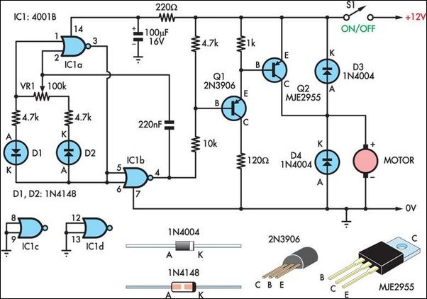
Two Basic Motor Speed Controllers
Two simple 12V DC motor speed controllers can be constructed for a minimal cost. These controllers take advantage of the principle that the rotational speed of a DC motor is directly proportional to the average value of its supply voltage....
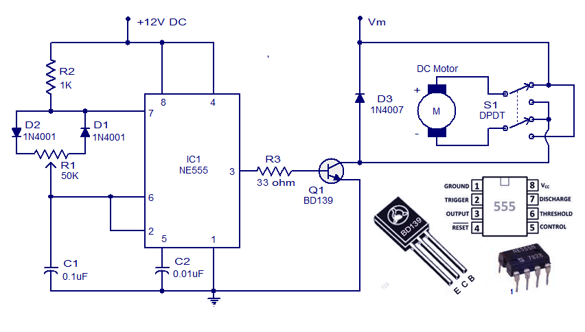
DC Motor Controller Circuit with NE555
This weblog discusses electronic circuit schematics, PCB design, DIY kits, and electronic project diagrams. A simple DC motor controller circuit utilizing the NE555 timer is presented. Several DC motor speed control circuits are explored, with this being the first example...

DC Motor Control
The circuit operates a small motor for opening and closing a pair of curtains. The DC motor consists of six basic components: commutator, stator, rotor (also known as armature), axle, field magnet(s), and brushes. Key components include LED, diode, resistor,...
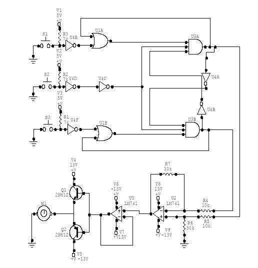
DC Motor Controller
This DC Motor Controller circuit will control a 12V dc motor. The system will have three pushbuttons: a START button, a REVERSE button and a STOP button. Initially, the motor must not be running. When the START button is pressed,...
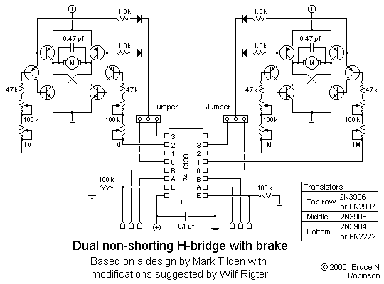
Full-featured Dual H-bridge
This is a slightly revised version of the 6-transistor H-bridge designed by Mark Tilden and found on the BEAM Tek website (now only available via archive). I encourage anyone interested in H-bridges to read Mark's article, as it gives an...
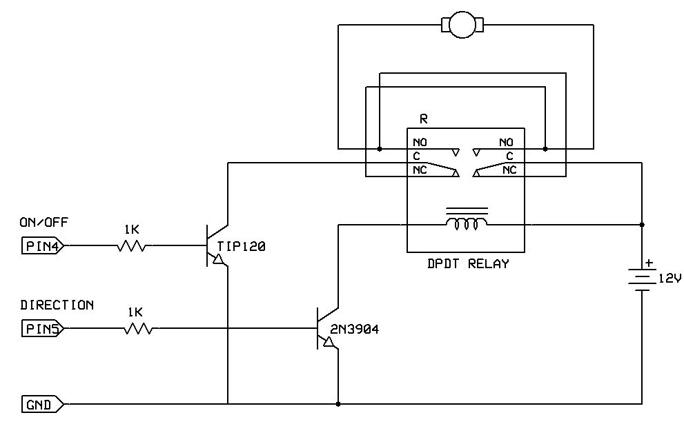
Bidirectional motor control
One of the simplest methods to enable a motor to rotate in both directions is by utilizing a double-pole, double-throw (DPDT) relay. This setup requires two transistors and two Stamp pins: one for on/off control and the other for direction...
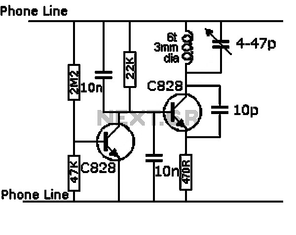
motor driver circuit
These circuits are commonly utilized in robotics to enable DC motors to operate in both forward and reverse directions, as well as to provide an electric brake (short circuit condition). H-bridges can be found as integrated circuits or can be...
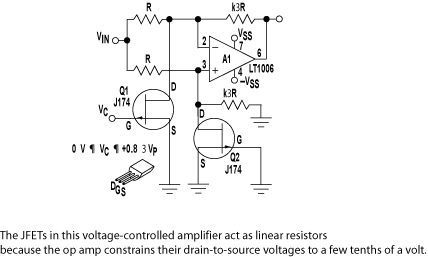
Control circuit keeps dc motor running at constant speed
The purpose of this circuit is to maintain a permanent magnet DC motor at a constant speed, which is set externally. This is achieved by monitoring the current flowing through and the voltage across the motor's brushes.
The schematic for this...
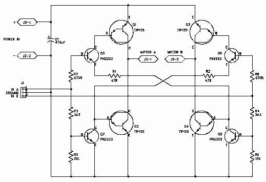
H-Bridge
H-Bridge
This circuit drives small DC motors up to about 100 watts or 5 amps or 40 volts, whichever comes first. Using bigger parts could make it more powerful. Using a real H-bridge IC makes sense for this size of motor,...