


Chemical mixer circuit
#chemical mixer
#stirring speed
#thermostat
#timer alarm
#heating
#magnetic stir
#industrial
#automation
#control circuit
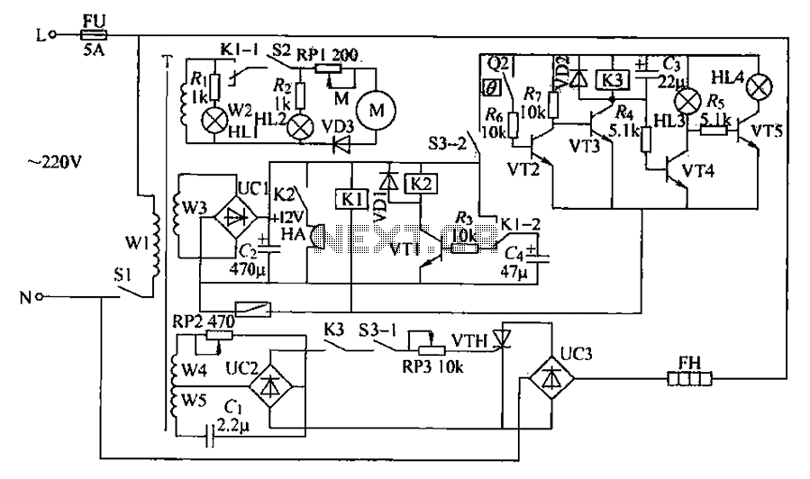
Description: A chemical mixer circuit equipped with stirring speed control, a thermostat, and a timer alarm function is suitable for use in the chemical, steel, and other industries. The circuit includes components for heating, magnetic stirring, motor control, and timing alarms.
The power circuit is initiated by a power switch (S1) and includes a power transformer (T), a rectifier bridge (UC1), a resistor (R), and a filter capacitor, along with a power indicator (HL1). The heating thermostat circuit is controlled by switch (S3) and includes an electric contact thermometer (Q2), resistors, capacitors (C1 and C2), transistors (VT2-VT5), an electric heater (EH), a thermostat indicator (HL3), a heating indicator (HL4), a diode (VD2), a relay (K3), and potentiometers (RP1 and RP3). The time alarm circuit consists of a transistor (VT1), resistors (R3), a capacitor (C0), a relay (K2), a diode (VD1), a buzzer (HA), and control contacts (K1-2). The stirring motor speed control circuit is managed by switch (S2), potentiometer (RP1), resistor (R2), diode (VD3), stirring indicator (HL2), and the electric motor (M). The timing control circuit is composed of a timer and relays (K1 and Q1).
When the power switch (S1) is turned on, an AC voltage of 220V is supplied by transformer (T) through three groups of AC voltage windings (W2 to W5). The W3 winding provides AC voltage to rectifier (UC1), which filters and supplies +12V power to the timing circuit, delay alarm circuit, and temperature control circuit. Upon activation of the timer (Q1), relay (K1) engages, disconnecting normally closed contacts (K1-1 and K1-2) and connecting the normally open contact to charge capacitor (C1).
Switching on (S2) generates AC voltage from winding (W2), which is rectified by diode (VD3) and limited by resistor (RP1) to supply the stirring motor (M), driving the stirring blades for mixing operations. Activating switch (S3) causes transistor (VT3) to conduct, energizing relay (K3) and connecting its normally open contact. The windings (W4 and W5) generate AC voltage, which flows through capacitor (C1) and resistor (RP2) to be rectified by (UC2) via the normally open contact of (K3) and switch (S3-1). Potentiometer (RP3) provides the trigger voltage to thyristor (VTH), which is activated to supply AC voltage through (UC3) to the electric heater (EH).
The stirring motor speed can be adjusted by varying the resistance of potentiometer (RP1), thereby altering the working voltage and achieving a variable stirring speed. By adjusting resistances (RP2 and RP3), the conduction angle of (VTH) can be modified, which in turn changes the operating voltage of the electric heater (EH), allowing for stepless temperature control.
The electric contact thermometer (Q2) maintains temperature regulation. If the heating temperature falls below the set threshold, (Q2) remains disconnected, preventing power to (V2). Once the temperature reaches the preset value, the contacts of (Q2) close, allowing (VT2) to conduct, which deactivates (VT3) and releases relay (K3). This action cuts off power to (VTH) and stops heating (EH). Concurrently, (VT4) conducts while (VT5) turns off, illuminating indicator (HL3) and turning off (HL4), thus achieving automatic temperature control. Chemical mixer circuit having a stirring speed, thermostat and timer alarm function can be used in chemical, steel and other industries. (1) circuit works heating magnetic stir rer circuit from the power circuit, stirring motor control circuit, heating thermostat circuit, stirring motor speed control circuit, a timing alarm circuit and the timing control circuit, shown in Figure 7-11. Power circuit from the power switch Sl, the power transformer T, rectifier bridge UC1, resistor R., And a filter capacitor power indicator HL1 island components.
Heating thermostat heating circuit by the control switch S3 (S3-1. S3-2), electric contact thermometer Q2, resistors brother ~ Island, capacitance c] and Ca, crystal transistor VT2-VT5, electric heater EH, thermostat indicator HL3, heating indicator HIA, diode VD2, relay K3, potentiometer RI Yi and RP3, bridge rectifiers and thyristors VTH UC2 and UC3 composition. Time alarm circuit by the transistor VT1, resistors R3, capacitor 0, relay K2, the diode VD1, buzzer HA and Kl control contacts Kl-2 components.
Stirred by the stirring motor speed control circuit controls the switch S2, potentiometer RP1, resistor R2, diode VD3, stirring indicator HL2 and electric motor M components. : Timing control circuit by the timer and relays Kl Ql composition. Turn the power switch S], AC 220V voltage by T Buck, produced three groups AC voltage winding W2 ~ W5.
W3 winding -UC1 alternating voltage rectifier, filter G, Zhu is a timing circuit, delay alarm circuit and temperature control circuit provides + 12V power supply. After switching on the timer Ql, relay Kl pull power, Kl-l and Kl-2 normally closed contacts disconnect normally open contact connected, cI charge.
After switching S2, produced on the T winding W2 AC voltage rectified by VD3 and RP1 after limiting supply buck stirring motor M, M drive moving stirring blades into the mixing operation. After switching S3, VT3 conduction, K3 pull power, and its normally open contact connected, Ts W4, w5 winding AC voltage generated by Cl and RP2 flow limit, after UC2 rectified by K3 normally open contact and S3-1.
RP3 provide VTH trigger voltage, the VTH is turned on, AC 220V voltage by UC3 and VTH for the electric heater EH provide operating voltage. Adjust the resistance of RP1 can change the M working voltage level, thereby changing the speed of the stirring speed, variable speed to achieve the purpose.
Adjusting section RP2 and RP3 resistance, can change VTH conduction angle, thus changing EH working voltage level, stepless temperature reaches purposes. When the heating temperature is lower than the value of electric contact thermometer temperature control set Q2, Q2 electric contact in a disconnected state, V2 off.
When the heating temperature reaches the set temperature control Q2, electric contacts Q2 is turned on, so that VT2 conduction, VT3 deadline, K3 release, VTH cut stop, EH power to stop heating. Meanwhile VT4 conduction. VT5 off, HL3 lit, HL4 off, so as to achieve the purpose of automatic temperature control.
The power circuit is initiated by a power switch (S1) and includes a power transformer (T), a rectifier bridge (UC1), a resistor (R), and a filter capacitor, along with a power indicator (HL1). The heating thermostat circuit is controlled by switch (S3) and includes an electric contact thermometer (Q2), resistors, capacitors (C1 and C2), transistors (VT2-VT5), an electric heater (EH), a thermostat indicator (HL3), a heating indicator (HL4), a diode (VD2), a relay (K3), and potentiometers (RP1 and RP3). The time alarm circuit consists of a transistor (VT1), resistors (R3), a capacitor (C0), a relay (K2), a diode (VD1), a buzzer (HA), and control contacts (K1-2). The stirring motor speed control circuit is managed by switch (S2), potentiometer (RP1), resistor (R2), diode (VD3), stirring indicator (HL2), and the electric motor (M). The timing control circuit is composed of a timer and relays (K1 and Q1).
When the power switch (S1) is turned on, an AC voltage of 220V is supplied by transformer (T) through three groups of AC voltage windings (W2 to W5). The W3 winding provides AC voltage to rectifier (UC1), which filters and supplies +12V power to the timing circuit, delay alarm circuit, and temperature control circuit. Upon activation of the timer (Q1), relay (K1) engages, disconnecting normally closed contacts (K1-1 and K1-2) and connecting the normally open contact to charge capacitor (C1).
Switching on (S2) generates AC voltage from winding (W2), which is rectified by diode (VD3) and limited by resistor (RP1) to supply the stirring motor (M), driving the stirring blades for mixing operations. Activating switch (S3) causes transistor (VT3) to conduct, energizing relay (K3) and connecting its normally open contact. The windings (W4 and W5) generate AC voltage, which flows through capacitor (C1) and resistor (RP2) to be rectified by (UC2) via the normally open contact of (K3) and switch (S3-1). Potentiometer (RP3) provides the trigger voltage to thyristor (VTH), which is activated to supply AC voltage through (UC3) to the electric heater (EH).
The stirring motor speed can be adjusted by varying the resistance of potentiometer (RP1), thereby altering the working voltage and achieving a variable stirring speed. By adjusting resistances (RP2 and RP3), the conduction angle of (VTH) can be modified, which in turn changes the operating voltage of the electric heater (EH), allowing for stepless temperature control.
The electric contact thermometer (Q2) maintains temperature regulation. If the heating temperature falls below the set threshold, (Q2) remains disconnected, preventing power to (V2). Once the temperature reaches the preset value, the contacts of (Q2) close, allowing (VT2) to conduct, which deactivates (VT3) and releases relay (K3). This action cuts off power to (VTH) and stops heating (EH). Concurrently, (VT4) conducts while (VT5) turns off, illuminating indicator (HL3) and turning off (HL4), thus achieving automatic temperature control. Chemical mixer circuit having a stirring speed, thermostat and timer alarm function can be used in chemical, steel and other industries. (1) circuit works heating magnetic stir rer circuit from the power circuit, stirring motor control circuit, heating thermostat circuit, stirring motor speed control circuit, a timing alarm circuit and the timing control circuit, shown in Figure 7-11. Power circuit from the power switch Sl, the power transformer T, rectifier bridge UC1, resistor R., And a filter capacitor power indicator HL1 island components.
Heating thermostat heating circuit by the control switch S3 (S3-1. S3-2), electric contact thermometer Q2, resistors brother ~ Island, capacitance c] and Ca, crystal transistor VT2-VT5, electric heater EH, thermostat indicator HL3, heating indicator HIA, diode VD2, relay K3, potentiometer RI Yi and RP3, bridge rectifiers and thyristors VTH UC2 and UC3 composition. Time alarm circuit by the transistor VT1, resistors R3, capacitor 0, relay K2, the diode VD1, buzzer HA and Kl control contacts Kl-2 components.
Stirred by the stirring motor speed control circuit controls the switch S2, potentiometer RP1, resistor R2, diode VD3, stirring indicator HL2 and electric motor M components. : Timing control circuit by the timer and relays Kl Ql composition. Turn the power switch S], AC 220V voltage by T Buck, produced three groups AC voltage winding W2 ~ W5.
W3 winding -UC1 alternating voltage rectifier, filter G, Zhu is a timing circuit, delay alarm circuit and temperature control circuit provides + 12V power supply. After switching on the timer Ql, relay Kl pull power, Kl-l and Kl-2 normally closed contacts disconnect normally open contact connected, cI charge.
After switching S2, produced on the T winding W2 AC voltage rectified by VD3 and RP1 after limiting supply buck stirring motor M, M drive moving stirring blades into the mixing operation. After switching S3, VT3 conduction, K3 pull power, and its normally open contact connected, Ts W4, w5 winding AC voltage generated by Cl and RP2 flow limit, after UC2 rectified by K3 normally open contact and S3-1.
RP3 provide VTH trigger voltage, the VTH is turned on, AC 220V voltage by UC3 and VTH for the electric heater EH provide operating voltage. Adjust the resistance of RP1 can change the M working voltage level, thereby changing the speed of the stirring speed, variable speed to achieve the purpose.
Adjusting section RP2 and RP3 resistance, can change VTH conduction angle, thus changing EH working voltage level, stepless temperature reaches purposes. When the heating temperature is lower than the value of electric contact thermometer temperature control set Q2, Q2 electric contact in a disconnected state, V2 off.
When the heating temperature reaches the set temperature control Q2, electric contacts Q2 is turned on, so that VT2 conduction, VT3 deadline, K3 release, VTH cut stop, EH power to stop heating. Meanwhile VT4 conduction. VT5 off, HL3 lit, HL4 off, so as to achieve the purpose of automatic temperature control.
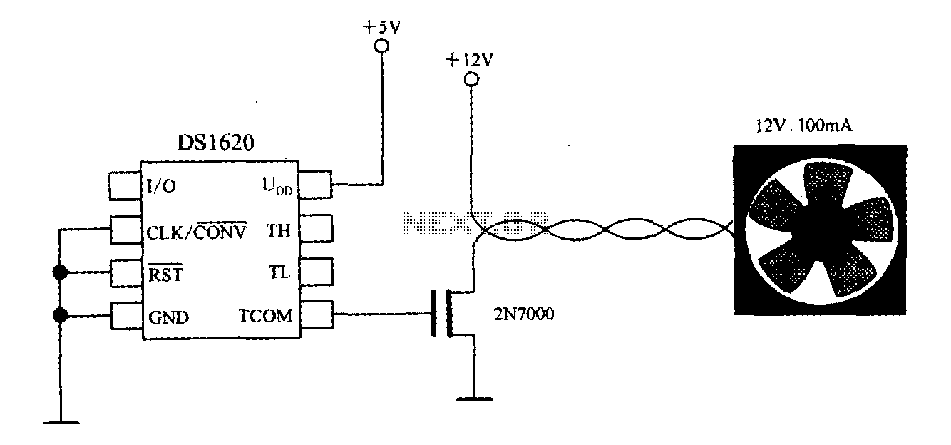
Thermostat with three-wire serial interface smart temperature sensor DS1620 configuration control circuit
The DS1620, in conjunction with a microprocessor, is utilized to monitor temperature. By controlling the fan, the thermal conditions of the chip can be adjusted to establish a temperature control circuit as illustrated in the accompanying figure. The system is...
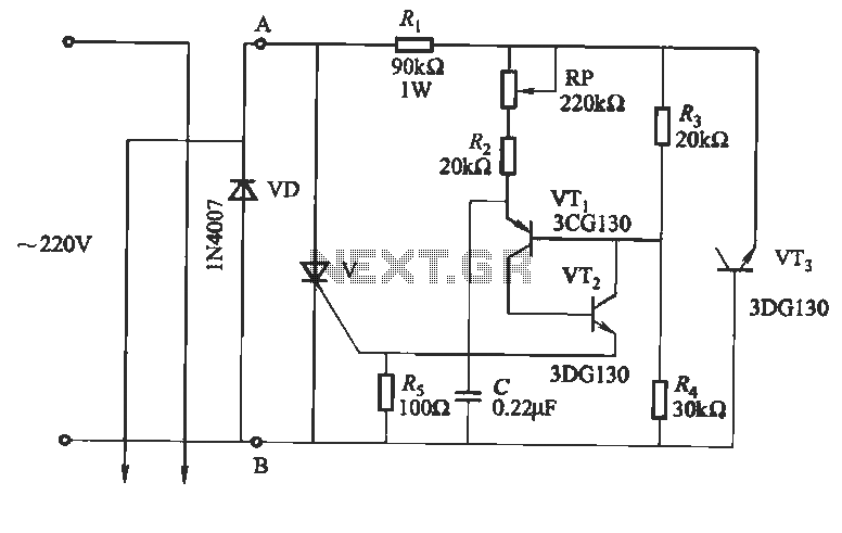
Manual thermostat circuit
This circuit utilizes an "and other potential triggers" circuit. The term equipotential trigger refers to a crystal bidirectional thyristor trigger, which can be activated by either a positive or negative trigger. In this setup, the control electrode G and the...
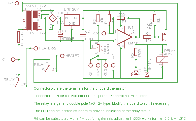
Thermostat Circuits
Affordable, straightforward, and precise thermostat circuits with instructions.
The thermostat circuit is designed to provide a cost-effective and reliable solution for temperature control applications. It typically utilizes a temperature sensor, such as a thermistor or a thermocouple, to monitor the ambient...
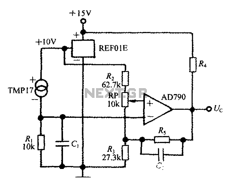
Adjustable thermostat controller circuit diagram created REF01E
An adjustable thermostat controller circuit is widely used in everyday applications, such as for maintaining a constant temperature in soldering irons. The circuit utilizes the TMP17 sensor along with the REF01E voltage reference to ensure a stable 10V supply voltage....
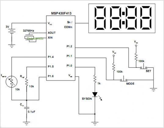
Implementing An Ultralow-power Thermostat With Slope A/d Conversion
More:
A comprehensive electronic schematic that outlines the design and functionality of a specific circuit is crucial for understanding its operation. The schematic should include components such as resistors, capacitors, diodes, transistors, and integrated circuits, along with their interconnections. Each...
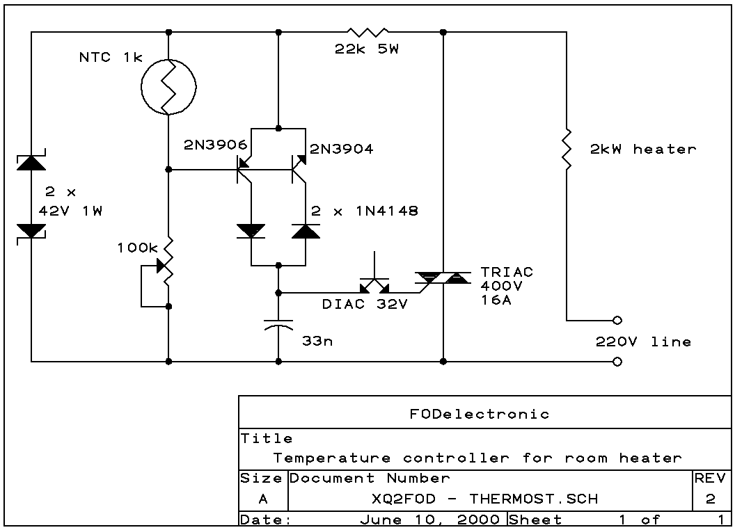
Electronic Thermostat
Here is a circuit that implements phase-control of heaters, adjusting their power smoothly from zero to around 95% of the rated power, keeping the room temperature to within 1 or 2 degrees, while using few components. Notice that this is...
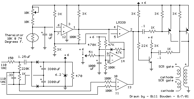
1000 Watt Thermostat controller
Below is a thermostat circuit I recently built to control a 1300 watt space heater. The heater element (not shown) is connected in series with two back to back 16 amp SCRs (not shown) which are controlled with a small...
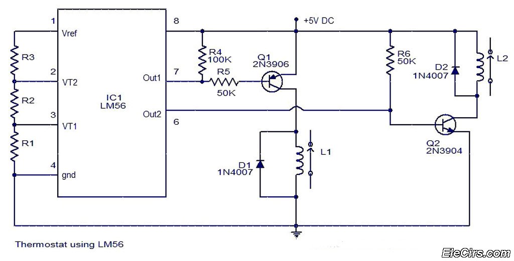
Audio Thermostat LM56 ProjectCircuit
The LM56 Thermostat Project Circuit Diagram includes a schematic for the LM56 thermostat. The values of resistors R1, R2, and R3, which determine the required trip points VT1 and VT2, can be calculated using the following equations: VT1 = 1.250V...
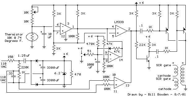
Thermostat for 1KW Space Heater (SCR controlled) circuit
The heating element is connected in series with two back-to-back 16 amp silicon-controlled rectifiers (SCRs), which are controlled by a small pulse transformer. This pulse transformer features three identical windings; two of these windings provide trigger pulses to the SCRs,...