


DC Motor Control Circuit
#DC motor
#TIP31 transistors
#push button switches
#back EMF diodes
#curtain control
#12V motor
#1N4001 diodes
#direction indication
#load current
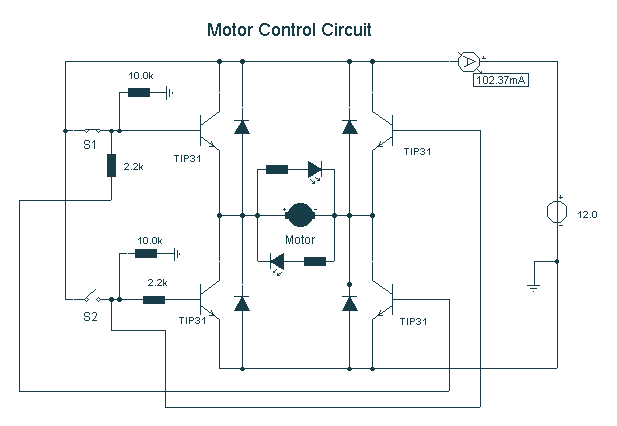
Description: Here, S1 and S2 are normally open, push to close, press button switches. The diodes can be red or green and are there only to indicate direction. You may need to alter the TIP31 transistors depending on the motor being used. Remember, running under load draws more current. This circuit was built to operate a small motor used for opening and closing a pair of curtains. As an advantage over automatic closing and opening systems, you have control of how much, or how little light to let into a room. The four diodes surrounding the motor are back EMF diodes. They are chosen to suit the motor. For a 12V motor drawing 1 amp under load, I use 1N4001 diodes.
The described circuit utilizes two normally open push-button switches, S1 and S2, which serve as user controls for operating a small motor responsible for opening and closing curtains. When either switch is pressed, it completes the circuit, allowing current to flow and activating the motor. The configuration permits the user to control the position of the curtains, providing flexibility in managing light levels within a room, unlike fully automated systems.
The circuit incorporates diodes, which may be red or green for visual indication of the direction of motor operation. These diodes are essential for ensuring that the current flows in the intended direction and provides feedback to the user regarding the state of the circuit.
The use of TIP31 transistors is crucial for switching the motor on and off, and it is important to select transistors that can handle the current requirements of the specific motor being utilized. The TIP31 is a power transistor that can manage higher currents, but it may need to be substituted based on the motor's specifications, especially if the motor operates under load, which increases the current draw.
Back EMF diodes are integrated into the circuit to protect the transistors from voltage spikes generated when the motor is turned off. These spikes can damage the transistors if not properly managed. The choice of diodes, such as the 1N4001, is appropriate for a 12V motor drawing 1 amp under load, as they are rated for sufficient reverse voltage and current handling.
Overall, this circuit design provides a practical solution for controlling a small motor in a curtain application, combining user control with protective measures to ensure reliable operation.Here, S1 and S2 are normally open , push to close, press button switches. The diodes can be red or green and are there only to indicate direction. You may need to alter the TIP31 transistors depending on the motor being used. Remember, running under load draws more current. This circuit was built to operate a small motor used for opening and closing a pair of curtains. As an advantage over automatic closing and opening systems, you have control of how much, or how little light to let into a room. The four diodes surriunding the motor, are back EMF diodes. They are chosen to suit the motor. For a 12V motor drawing 1amp under load, I use 1N4001 diodes.
The described circuit utilizes two normally open push-button switches, S1 and S2, which serve as user controls for operating a small motor responsible for opening and closing curtains. When either switch is pressed, it completes the circuit, allowing current to flow and activating the motor. The configuration permits the user to control the position of the curtains, providing flexibility in managing light levels within a room, unlike fully automated systems.
The circuit incorporates diodes, which may be red or green for visual indication of the direction of motor operation. These diodes are essential for ensuring that the current flows in the intended direction and provides feedback to the user regarding the state of the circuit.
The use of TIP31 transistors is crucial for switching the motor on and off, and it is important to select transistors that can handle the current requirements of the specific motor being utilized. The TIP31 is a power transistor that can manage higher currents, but it may need to be substituted based on the motor's specifications, especially if the motor operates under load, which increases the current draw.
Back EMF diodes are integrated into the circuit to protect the transistors from voltage spikes generated when the motor is turned off. These spikes can damage the transistors if not properly managed. The choice of diodes, such as the 1N4001, is appropriate for a 12V motor drawing 1 amp under load, as they are rated for sufficient reverse voltage and current handling.
Overall, this circuit design provides a practical solution for controlling a small motor in a curtain application, combining user control with protective measures to ensure reliable operation.Here, S1 and S2 are normally open , push to close, press button switches. The diodes can be red or green and are there only to indicate direction. You may need to alter the TIP31 transistors depending on the motor being used. Remember, running under load draws more current. This circuit was built to operate a small motor used for opening and closing a pair of curtains. As an advantage over automatic closing and opening systems, you have control of how much, or how little light to let into a room. The four diodes surriunding the motor, are back EMF diodes. They are chosen to suit the motor. For a 12V motor drawing 1amp under load, I use 1N4001 diodes.
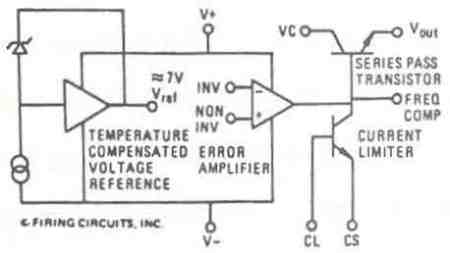
Model 1681 Instruction Manual
This manual applies to all integral horsepower DC motor controls within this series, ranging from 40 HP to 300 HP. The integrated circuit regulator selection of these DC motor controls is modular in construction, allowing for minimal downtime in the...
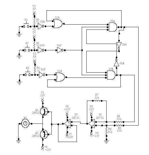
DC Motor Controller
This DC Motor Controller circuit will control a 12V dc motor. The system will have three pushbuttons: a START button, a REVERSE button and a STOP button. Initially, the motor must not be running. When the START button is pressed,...
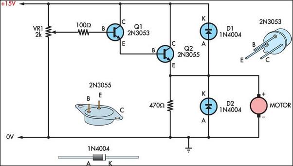
Two Basic Motor Speed Controllers
Two simple 12V DC motor speed controllers can be constructed for a minimal cost. These controllers take advantage of the principle that the rotational speed of a DC motor...
DC motor speed controllers are essential components in various applications where precise...
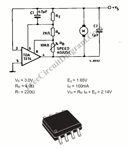
Small DC Motor Speed Controller
Electric motors have been widely used for motion control, and various types of motor controllers have been designed to provide variable speed drives for these motors.
Electric motors are integral to numerous applications requiring precise motion control, ranging from industrial automation...
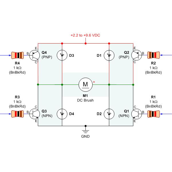
the dc motor circuit
Selecting the appropriate DC motor is essential for constructing mobile robots. Testing DC motors is straightforward and can be accomplished by assembling a basic DC motor circuit. The components needed for this circuit include a DC motor, a battery power...
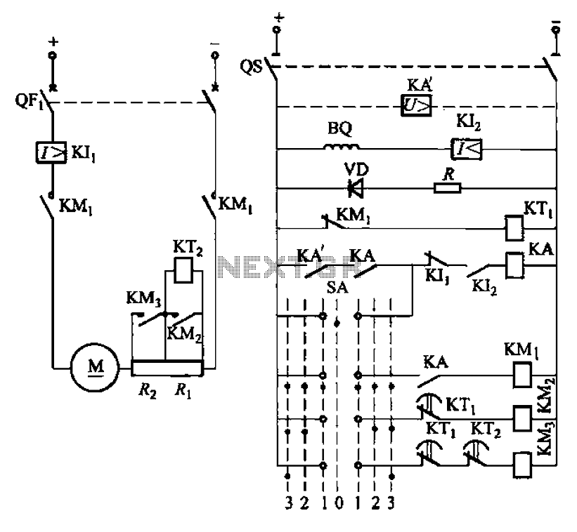
One of debug circuitry DC motor armature resistance in series starting
The circuit depicted in Figure 3-190 includes an armature circuit with two startup resistors, Ri and Rz, connected in series through the main switch SA to facilitate starting, stopping, and speed control. During the startup phase, two relays, KTi and...
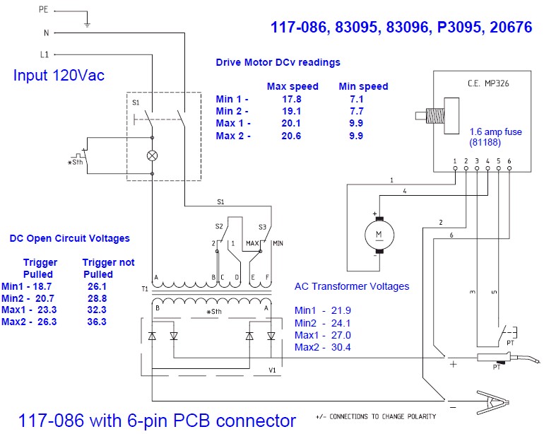
Need Help Deciphering Circuit Board Schematic
The wire speed DC motor consistently receives approximately 20 volts, irrespective of the switch position on the nozzle handle. The switch has been tested with an ohmmeter and functions properly. Even after disconnecting the switch from the circuit board, the...
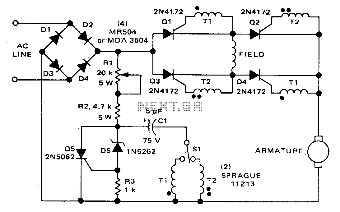
Direction and speed control for series-wound motors
The circuit can control the speed and direction of rotation of a series-wound DC motor. Silicon controlled rectifiers Q1-Q4 are arranged in a bridge configuration and are triggered in diagonal pairs. The selection of which pair to activate is managed...
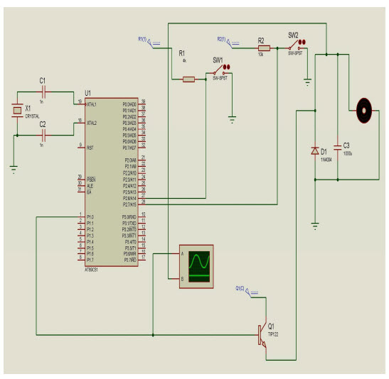
Speed Control of DC Motor using Microcontroller 8051 withCircuit
The objective of this project is to control the speed of a DC motor. The primary benefit of utilizing a DC motor is the ability to modify the Speed-Torque relationship to nearly any desired form. To facilitate speed control, an...