


Designing Robust and Fault-Tolerant Motion-Control Feedback Systems
#servo systems
#feedback systems
#encoder
#controller receiver
#PC-board layout
#industrial feedback
#fault-tolerant
#motion control
#signal cable
#termination

Description: This article reviews basic servo systems and the development of fault-tolerant feedback systems for servo applications. It discusses controller receiver circuit design, appropriate PC-board receiver circuit layout, and the encoder's signal cable and termination. Various types of industrial feedback encoders are presented, along with the different types of faults that can develop in a servo feedback system. The key to robust operation in such systems lies in their ability to handle mechanical and electrical faults. This article outlines the design of a robust and fault-tolerant motion-control system that incorporates quadrature encoders in its feedback paths. Modern automated systems utilize closed-loop feedback for motion control, typically comprising a servo system that includes a motor driver and feedback elements, which together provide accurate and stable control over speed and position. The various system-level components of a typical servo system are illustrated in a referenced figure. DC brushless motors are favored for high-performance and high-speed applications, while DC brush and stepper motors are suitable for low-speed and less-demanding applications. Brushless motors are assumed throughout this article and usually feature a quadrature encoder at the end of the shaft to determine the shaft velocity and commutation point for controlling the motor's coil-switching sequences. A second quadrature encoder on the machine's rotating shaft provides position data, which may differ from the motor-shaft position due to inaccuracies from backlash in gearhead and lead-screw assemblies. Typical motion-controller cards and modules include a motion-control IC, a microprocessor, and a DSP or custom ASIC for processing high-speed encoder signals. The controller generates velocity and direction-of-rotation signals for the driver or amplifier, which in turn supplies the necessary voltage and current levels to operate the motor. To design a robust and fault-tolerant motion-control system with feedback, several system-level considerations must be addressed during the design phase. Although not covered in this article, motion-controller inputs such as hard-wired emergency stop and limit inputs should also be factored into the design of a fault-tolerant feedback system. The motor's quadrature encoder transmits six RS-422/RS-485 signals (A, A, B, B, Index, and Index) through the cable to the motion controller's receiver circuit (the encoder input). The receiver converts the RS-422 signals to logic-level signals, assuming RS-422 due to the presence of a single transmitter, and feeds them to the motion-controller circuit for processing. The receiver circuit must be capable of responding to various faults in the servo-system environment, including opens, shorts, and noise. A specific figure illustrates the encoder-input receiver circuit in a typical motion controller. The device used is a 10Mbps, 5V, quad RS-422/RS-485 receiver with ±15kV ESD protection. For fault-tolerant systems with encoder inputs connected to external components, ESD protection is essential. The lack of external ESD-protection components significantly reduces the PC-board area required for this circuit. The encoder-input receiver circuit features open-line detection and ESD protection on all encoder input lines. The termination resistors provide proper termination for each group of complementary signal pairs transmitted down the twisted-pair cable from the quadrature encoder. Issues related to cable termination are addressed in detail later. A break or disconnect in the cable results in an open-circuit fault that must be detected before the motion control system can function correctly.
The design of a fault-tolerant servo system requires a comprehensive understanding of the components involved and their interactions. The servo system typically includes a motor driver, feedback elements, and a controller that processes the feedback signals. The motor driver receives commands from the controller, which are based on the feedback signals generated by the quadrature encoders. These encoders provide crucial information about motor position and speed, allowing for precise control.
The receiver circuit plays a vital role in ensuring reliable communication between the encoders and the controller. It must effectively convert the differential signals from the encoders into logic-level signals, which are then processed by the controller. The inclusion of ESD protection within the receiver circuit is critical for safeguarding against electrical disturbances that could otherwise lead to system failures.
Additionally, the layout of the PCB must be optimized to minimize noise and interference, which can impact the performance of the servo system. Proper grounding techniques and the use of twisted-pair cables for signal transmission can significantly enhance the system's reliability.
The selection of the appropriate motor type is also essential. While DC brushless motors are ideal for high-performance applications due to their efficiency and reliability, other motor types may be used depending on the specific requirements of the application. Each motor type has its characteristics and advantages, which must be considered during the design phase.
In summary, a robust and fault-tolerant motion-control system must incorporate effective feedback mechanisms, reliable receiver circuits, and careful PCB design to ensure optimal performance and resilience against faults. The integration of these elements is crucial for achieving high levels of accuracy and stability in automated motion control applications.This article reviews basic servo systems and development of the fault-tolerant feedback systems for servo systems. Controller receiver circuit design, proper PC-board receiver circuit layout, and the encoder`s signal cable and termination are discussed.
Additionally, various types of industrial feedback encoders are presented, along with the various types of faults that can develop in a servo feedback system. The key to robust operation in a system lies in the way it handles mechanical and electrical faults. This article discusses the design of a robust and fault-tolerant motion-control system whose feedback paths incorporate quadrature encoders. Modern automated systems incorporate closed-loop feedback for motion control. They typically include a servo system that consists of a motor driver and feedback elements combined in a manner that gives accurate and stable control over speed and position.
The various system-level components of a typical servo system are illustrated in Figure 1. DC brushless motors are preferred for high-performance and high-speed applications. DC brush and stepper motors are suitable for low-speed and less-demanding applications. Brushless motors are assumed throughout this article. Such motors typically include a quadrature encoder on the end shaft that determines the shaft velocity and commutation point for controlling the motor`s coil-switching sequences (see sidebar, Feedback encoder types). A second quadrature encoder on the machine`s rotating shaft provides position data for that shaft, which generally differs from the motor-shaft position due to inaccuracies caused by backlash in the gearhead and lead-screw assemblies.
Typical motion-controller cards and modules include a motion-control IC, a microprocessor, and a DSP or custom ASIC for processing the high-speed encoder signals. The controller provides velocity and direction-of-rotation signals to the driver or amplifier, which in turn provides the proper levels of voltage and current (power) to operate the motor.
To design a robust and fault-tolerant motion-control system with feedback, you must address the following items at the system level during design: Though not addressed in this article, motion-controller inputs, such as hard-wired emergency stop and limit inputs, should also be considered when designing a faulttolerant feedback system. The motor`s quadrature encoder sends six RS-422/RS-485 signals (A, A, B, B, Index, and Index) down the cable to the motion controller`s receiver circuit (the encoder input).
The receiver converts the RS-422 signals to logic-level signals (we assume RS-422 signals because the system has only one transmitter ), and feeds them to the motion-controller circuit for processing. (For RS-422 and RS-485 differences, refer to the short online tutorial RS-485 Basics at The receiver circuit must respond to various faults in the servo-system environment, including opens, shorts, and noise.
See the sidebar Fault types for information on faults and ESD. Figure 2 illustrates the encoder-input receiver circuit in a typical motion controller. U1 is a 10Mbps, 5V, quad RS-422/RS-485 receiver with ±15kV ESD protection. For fault-tolerant systems with encoder inputs that connect to external components, ESD protection is a must. The absence of external ESD-protection components substantially reduces the PC-board area required for this circuit.
Figure 2. Part of a motion controller, this encoder-input receiver circuit features open-line detection and ESD protection (internal to the MAX3095) on all encoder input lines. The 150 © resistors provide proper terminations for each group of complementary signal pairs transmitted down the twisted-pair cable from the quadrature encoder.
(Cable termination and related issues are covered in detail later. ) A break or disconnect in the cable produces an open-circuit fault that must be detected before the motion contr
The design of a fault-tolerant servo system requires a comprehensive understanding of the components involved and their interactions. The servo system typically includes a motor driver, feedback elements, and a controller that processes the feedback signals. The motor driver receives commands from the controller, which are based on the feedback signals generated by the quadrature encoders. These encoders provide crucial information about motor position and speed, allowing for precise control.
The receiver circuit plays a vital role in ensuring reliable communication between the encoders and the controller. It must effectively convert the differential signals from the encoders into logic-level signals, which are then processed by the controller. The inclusion of ESD protection within the receiver circuit is critical for safeguarding against electrical disturbances that could otherwise lead to system failures.
Additionally, the layout of the PCB must be optimized to minimize noise and interference, which can impact the performance of the servo system. Proper grounding techniques and the use of twisted-pair cables for signal transmission can significantly enhance the system's reliability.
The selection of the appropriate motor type is also essential. While DC brushless motors are ideal for high-performance applications due to their efficiency and reliability, other motor types may be used depending on the specific requirements of the application. Each motor type has its characteristics and advantages, which must be considered during the design phase.
In summary, a robust and fault-tolerant motion-control system must incorporate effective feedback mechanisms, reliable receiver circuits, and careful PCB design to ensure optimal performance and resilience against faults. The integration of these elements is crucial for achieving high levels of accuracy and stability in automated motion control applications.This article reviews basic servo systems and development of the fault-tolerant feedback systems for servo systems. Controller receiver circuit design, proper PC-board receiver circuit layout, and the encoder`s signal cable and termination are discussed.
Additionally, various types of industrial feedback encoders are presented, along with the various types of faults that can develop in a servo feedback system. The key to robust operation in a system lies in the way it handles mechanical and electrical faults. This article discusses the design of a robust and fault-tolerant motion-control system whose feedback paths incorporate quadrature encoders. Modern automated systems incorporate closed-loop feedback for motion control. They typically include a servo system that consists of a motor driver and feedback elements combined in a manner that gives accurate and stable control over speed and position.
The various system-level components of a typical servo system are illustrated in Figure 1. DC brushless motors are preferred for high-performance and high-speed applications. DC brush and stepper motors are suitable for low-speed and less-demanding applications. Brushless motors are assumed throughout this article. Such motors typically include a quadrature encoder on the end shaft that determines the shaft velocity and commutation point for controlling the motor`s coil-switching sequences (see sidebar, Feedback encoder types). A second quadrature encoder on the machine`s rotating shaft provides position data for that shaft, which generally differs from the motor-shaft position due to inaccuracies caused by backlash in the gearhead and lead-screw assemblies.
Typical motion-controller cards and modules include a motion-control IC, a microprocessor, and a DSP or custom ASIC for processing the high-speed encoder signals. The controller provides velocity and direction-of-rotation signals to the driver or amplifier, which in turn provides the proper levels of voltage and current (power) to operate the motor.
To design a robust and fault-tolerant motion-control system with feedback, you must address the following items at the system level during design: Though not addressed in this article, motion-controller inputs, such as hard-wired emergency stop and limit inputs, should also be considered when designing a faulttolerant feedback system. The motor`s quadrature encoder sends six RS-422/RS-485 signals (A, A, B, B, Index, and Index) down the cable to the motion controller`s receiver circuit (the encoder input).
The receiver converts the RS-422 signals to logic-level signals (we assume RS-422 signals because the system has only one transmitter ), and feeds them to the motion-controller circuit for processing. (For RS-422 and RS-485 differences, refer to the short online tutorial RS-485 Basics at The receiver circuit must respond to various faults in the servo-system environment, including opens, shorts, and noise.
See the sidebar Fault types for information on faults and ESD. Figure 2 illustrates the encoder-input receiver circuit in a typical motion controller. U1 is a 10Mbps, 5V, quad RS-422/RS-485 receiver with ±15kV ESD protection. For fault-tolerant systems with encoder inputs that connect to external components, ESD protection is a must. The absence of external ESD-protection components substantially reduces the PC-board area required for this circuit.
Figure 2. Part of a motion controller, this encoder-input receiver circuit features open-line detection and ESD protection (internal to the MAX3095) on all encoder input lines. The 150 © resistors provide proper terminations for each group of complementary signal pairs transmitted down the twisted-pair cable from the quadrature encoder.
(Cable termination and related issues are covered in detail later. ) A break or disconnect in the cable produces an open-circuit fault that must be detected before the motion contr
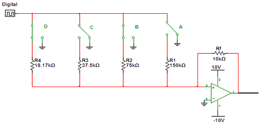
Encoder and Decoder
Encoders and decoders are circuits that convert analog signals to digital signals and digital signals to analog signals. The input is in digital form, while the output is a continuous sine wave or analog wave.
Encoders and decoders play a crucial...
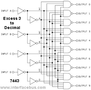
IC Excess-3 to Decimal Encoder Chip
The function diagram for both the 5443 and 5444 integrated circuits (ICs) is identical, assuming a 16-pin dual in-line package. The difference lies in their internal connections, as depicted in the functional schematic, and the method of input decoding. While...
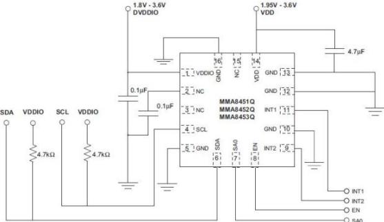
Motion Control Sensor Interface
The task involved implementing and programming all hardware devices to make data accessible to the receiver program running on a PC. This included configuring all Prospeckz devices and establishing protocols for radio transmission communication back to the PC. Additionally, the...
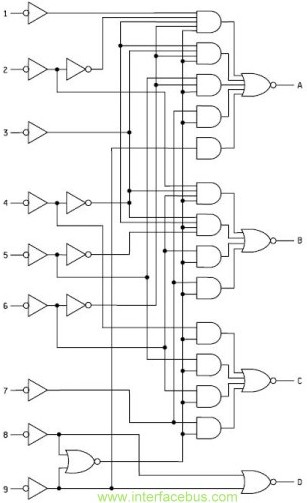
IC Encoder Chip
This function is not complex and can be easily implemented in a Programmable Logic Device (PLD) or Field Programmable Gate Array (FPGA). However, implementing this function in a small PLD may consume most of the device's I/O pins, which could...
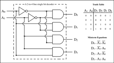
Combinational circuits Encoder Decoder
The Encoder and Decoder are different types of combinational circuits used to convert binary information to decimal, octal, and hexadecimal formats, and vice versa. A decoder is a combinational circuit that converts n-bit binary information into 2^n unique outputs. Therefore,...
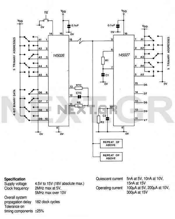
Remote control Encoder M145026B-1
This encoder can generate up to 19,683 codes from 9 address lines by detecting 1, 0, or an open circuit. To initiate the transmit sequence, pin 14 should be pulsed low. The encoder will output a data stream on pin...
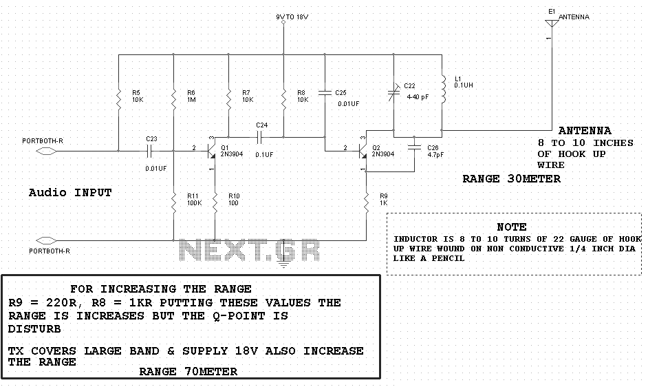
Encoder circuit for servos
The circuit is designed to fit snugly, eliminating the need for adhesive. It is recommended to test the fit multiple times, making incremental adjustments until a snug but movable fit is achieved. The entire circuit should be placed inside the...
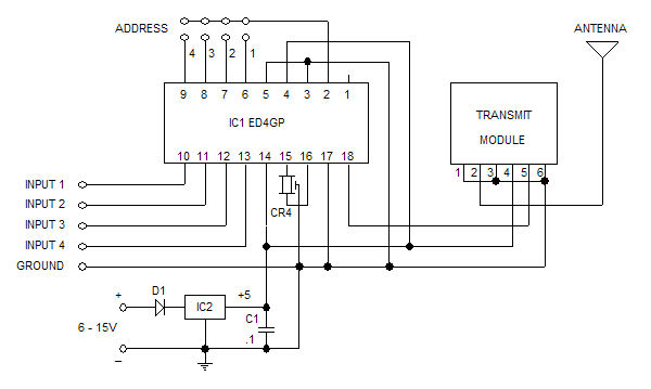
Glolab 4 Bit Encoder/Decoder for Wireless and Infrared
The Glolab ED4GP microprocessor-based Encoder/Decoder is designed for use with wireless modules, infrared remote controls, and other devices that operate with serial input and output data. It can function as either an encoder or a decoder by connecting pin 3...
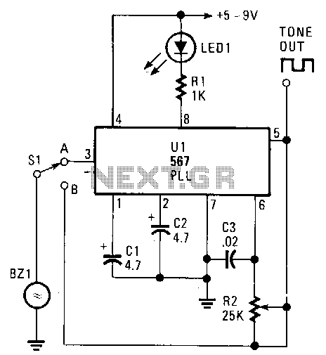
Encoder-decoder
The transducer circuit can function as either a tone encoder or decoder by adjusting the position of switch Sl. The operating frequency of this dual-purpose circuit is set by capacitors C3 and resistor R2. Capacitors C1 and C2 are not...